


Dry ice has plenty of applications in science and industry, most of which are based on these two well-known properties:
When exposed to atmospheric pressure, dry ice will cool down to -78.5°C (its sublimation temperature).
When sealed at room temperature, dry ice will pressurize the container to 57 bar (its vapour pressure).
For small-scale applications, dry ice can be produced by quickly venting liquid or gaseous CO2 from a pressurized canister. The adiabatic expansion produces flakes of dry ice which are captured in a cloth. The snow-like material is then packed into pellets.
A fire extinguisher containing 5 kg of pressurized CO2 sells for 80 EUR. Let's assume 50% of the CO2 is solidified during adiabatic expansion. Then this method produces dry ice for 32 EUR/kg.
According to thermodynamic data, gaseous CO2 at 20°C can be cooled to -78.5°C by extracting 81 kJ/kg, and then frozen by further extracting 571 kJ/kg. The coefficient of performance of an ideal cooler operating between -78.5°C and 20°C is 2 (and better at intermediate temperatures during the cool-down phase). Therefore the minimum theoretical work required to freeze CO2 is less than 326 kJ/kg, i.e. 0.09 kWh/kg, i.e. less than 0.02 EUR/kg. This is not significantly more expensive than turning water vapour into ice.
Thermodynamic cost of freezing CO2 and H2O, and liquefying N2

| ! |           |   Th |    Tc |       Cp |          L |      Qc |       R1W |  COP |       W |    cost |
|   |           | (°C) |  (°C) | (J/kg/K) |    (kJ/kg) | (kJ/kg) | (g/day/W) |      | (kJ/kg) | (EUR/t) |
|---+-----------+------+-------+----------+------------+---------+-----------+------+---------+---------|
| # | CO2(g->s) |   20 | -78.5 |      839 |        571 |    654. |      132. |  2.0 |    327. |    13.6 |
| # | H2O(l->s) |   20 |     0 |     4180 |        334 |    418. |      207. | 13.7 |     31. |     1.3 |
| # | H2O(g->s) |   20 |     0 |     4180 | (334+2265) |   2683. |       32. | 13.7 |    196. |     8.2 |
| # | N2(g->l)  |   20 |  -196 |     1040 |        200 |    425. |      203. |  0.4 |   1063. |    44.3 |
#+TBLFM: $7=($Th-$Tc)*$Cp/1000+$L;f0::$8=3600*24/$Qc;f0::$9=(273.15+$Tc)/($Th-$Tc);f1::$10=$Qc/$COP;f0::$11=($W/3600)*0.15*1000;f1
(Tables can be copy-pasted into Emacs Org-mode.)
Peltier modules are now commonly used in consumer products such as portable camping refrigerators and CPU heat sinks coolers. Amateur astronomers also use them to reduce thermal noise in image sensors.
The main weakness of thermoelectric coolers is their poor efficiency. However, even assuming a COP of 10^-3 (2000 times worse than the Carnot optimum), the cost of freezing CO2 would still be only 652 MJ/kg, i.e. 181 kWh/kg, i.e. about 27 EUR/kg. Therefore, thermoelectric production of dry ice could be as cost effective as the fire extinguisher method. It all depends on:
- whether Peltier modules can operate at -78.5°C
- how efficient they are at that temperature
- whether dry ice can be prevented from evaporating faster than it is produced.
Thermoelectric refrigeration is seldom mentioned for cryogenic temperatures, despite the need for compact, reliable solid-state devices in some applications. Cryocoolers typically rely on gas compression-expansion cycles. [RDR2011] mentions research toward thermoelectric cooling between a 80 K reservoir and 40 K load, so there is hope that commercially-available technology can already reach -80°C.


Temperatures are routinely measured with $5 type K thermocouples attached to $10 voltmeters. In theory this technique should work down to cryogenic temperatures, but for some reason any off-the-shelf device rated to probe below -50°C seems to cost at least $1000. So it was decided that this project would be started without such equipment, and that formation of dry ice would be sufficient proof of success.
Update . Inexpensive thermometers will typically display "Lo" when the temperature drops below their rated range. Some slightly more expensive models ship with detachable probes rated only for -30°C, but the main unit can apparently measure thermocouple voltages and display values down to -200°C. Even if the cheap probes become wildly inaccurate at -80°C, it should be possible to calibrate readings against a small sample of dry ice. This will be investigated.
Commercially-available Peltier modules typically have a maximum temperature difference of about 60 K. But modules can be stacked to produce larger differences.
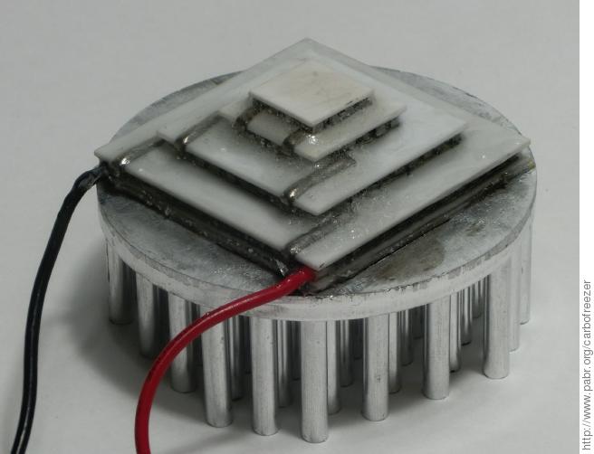
In a multi-stage device, each stage releases the heat it extracts from the previous stage, plus its own waste heat. For optimal efficiency, the stages must be carefully dimensioned with respect to each other. To save time and effort, a rather expensive four-stage off-the-shelf module was procured. It was sold unbranded and with barely any documentation, but this datasheet matches the main characteristics and provides detailed specifications. Dimensions are 35x35 mm (hot side), 10x10 mm (cold side), 10.7 mm height.
Operating parameters of interest are listed below:
TEC4-97-49-17-7-05 rated performance

| ! |   Th |  DT |   Tc |  Qc |   I |    U |
|   | (°C) | (K) | (°C) | (W) | (A) |  (V) |
|---+------+-----+------+-----+-----|------+
| # |   50 |   0 |   50 | 4.4 |     |      |
| # |   50 | 126 |  -76 |   0 | 4.4 | 12.6 |
| # |   27 |   0 |   27 | 4.0 |     |      |
| # |   27 | 112 |  -85 |   0 | 4.4 | 11.2 |
| # |   27 | 100 |  -73 | 0.4 | 4.4 |      |
| # |   27 |  90 |  -63 | 0.7 | 4.4 |      |
#+TBLFM: $4=$Th-$DT

On the one hand, the specifications suggest that -85°C can be reached simply by injecting 4.4 A into the module and keeping the hot side below 27°C. On the other hand, the cooling power will probably be as low as 0.1 W. This would freeze only 9 mg of CO2 per minute.
The module was attached with silver-based thermal paste to a 50x20 mm aluminium heat sink. Edges were sealed with epoxy resin in order to prevent moisture from damaging the elements. No effort was made to degas the epoxy before curing; hopefully the air bubbles will reduce thermal bridging.
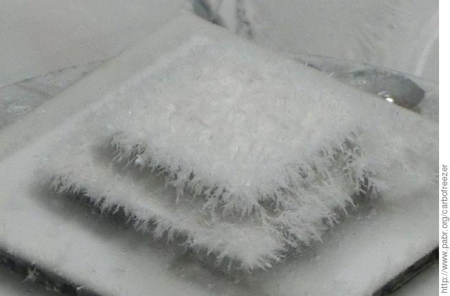
The module is very good at capturing water from ambient air (25°C, 50% relative humidity):
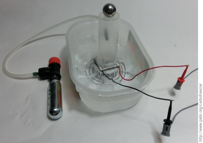


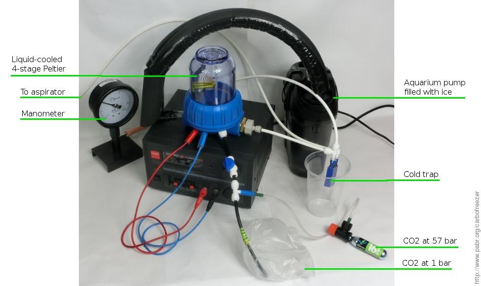
In this attempt the hot side of the Peltier module sits in a bath of ice cubes. The cold side protrudes into a chamber which is flushed with CO2 from a bicycle tire inflator.
No dry ice was obtained.
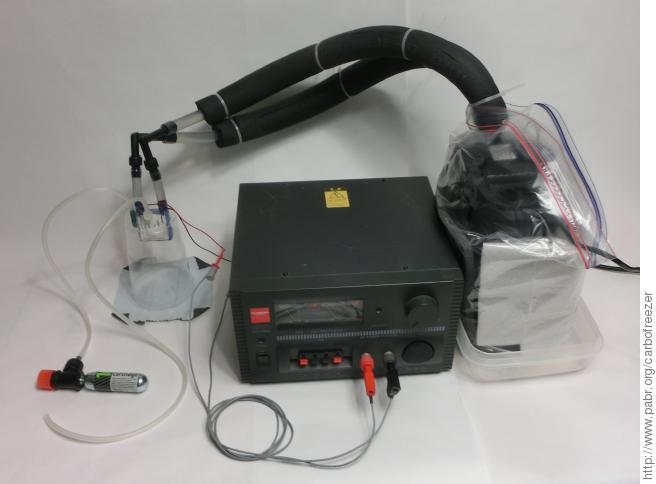


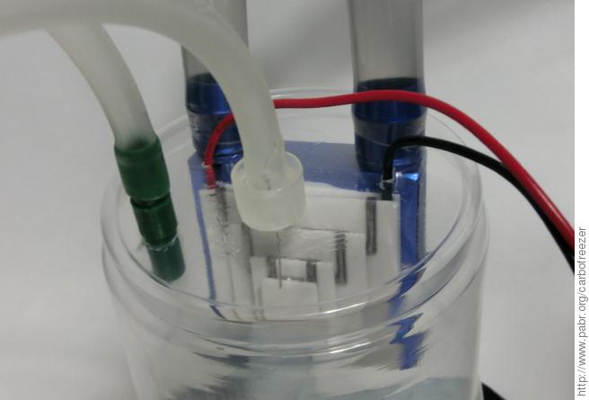
To improve heat extraction, another Peltier module was mounted on a liquid-cooled heat exchanger. Water is circulated by an aquarium canister pump filled with 1 kg of crushed water ice and 1 kg of tap water.
To prevent condensation of atmospheric moisture, the water lines are insulated and the pump is wrapped in packing foam and a plastic bag. The ice absorbs 50 W from the thermoelectric module plus 11 W from the pump itself. It can cool the heat exchanger to less than 5°C for about 30 minutes.
In this configuration the whole module is bathed in CO2, so there was no need to seal the edges with epoxy. Hopefully this reduces thermal bridging between the stages.
Again, no dry ice was obtained.
It was hoped that blowing moist air near the cold plate would at least produce snow, but this did not happen either. Presumably convection currents prevent the gas from getting cold enough.
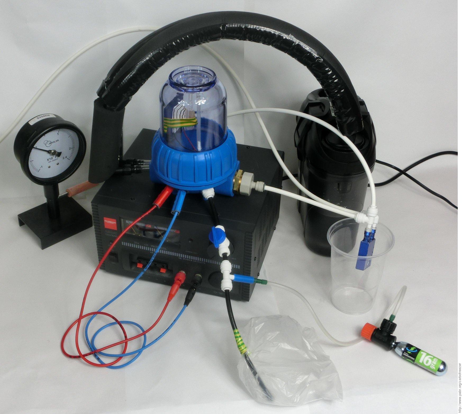


Next, a vacuum chamber was built out of plumbing supplies. It was expected that this would:
- reduce losses by convection and conduction around the module
- reduce thermal bridging within the module
The chamber itself is a water filter housing. These products usually have a screw-on bowl, which might damage the O-ring during tightening, so a slightly more expensive model with an unthreaded bowl and a ring nut was chosen instead.
The housing is rated for 5 bar outward pressure, presumably with a safety margin. Since the inner diameter is 88 mm, this means the bottom of the bowl, the ring nut and the cap can all handle 300 daN. Hopefully they will survive 1 bar of inward pressure when evacuated. All experiments were conducted behind a polycarbonate shield and with safety glasses anyway.
Presumably the housing is made of polyethylene terephthalate (PET) and polypropylene (PP), like soda bottles. These materials are notoriously difficult to bond with glue. The large hole where the coolant lines enter the chamber was plugged with epoxy resin. The other ports were sealed with hot-melt glue.


Coolant and gas connections were made with 1/4" and 3/8" push-fit fittings, which turned out to be usable for vacuum applications. The rigid polyethylene tubing does not collapse when evacuated, and the O-rings provide a reasonably good seal as long as the tubes are not bent and the surfaces are not scratched.

Vacuum is provided by a water aspirator. These devices can only pull a vacuum down to vapour pressure, i.e. about 30 mbar at room temperature. This should be sufficient for thermal insulation. However, water ice was still forming rapidly on the Peltier module, so a 0°C cold trap was inserted on the aspirator line. This reduced pressure from 50 mbar to 25 mbar (as measured by an inexpensive manometer, not accounting for fluctuations in atmospheric pressure). A significant amount of water ice can still be observed after 30 minutes of operation.
In a first attempt, the chamber was evacuated and then filled with CO2 at less than 100 mbar. It was hoped that the pressure would be low enough to improve thermal insulation, while still providing enough material for condensation. No dry ice was obtained. It was realized later that at 100 mbar the sublimation temperature of CO2 drops to -100°C.
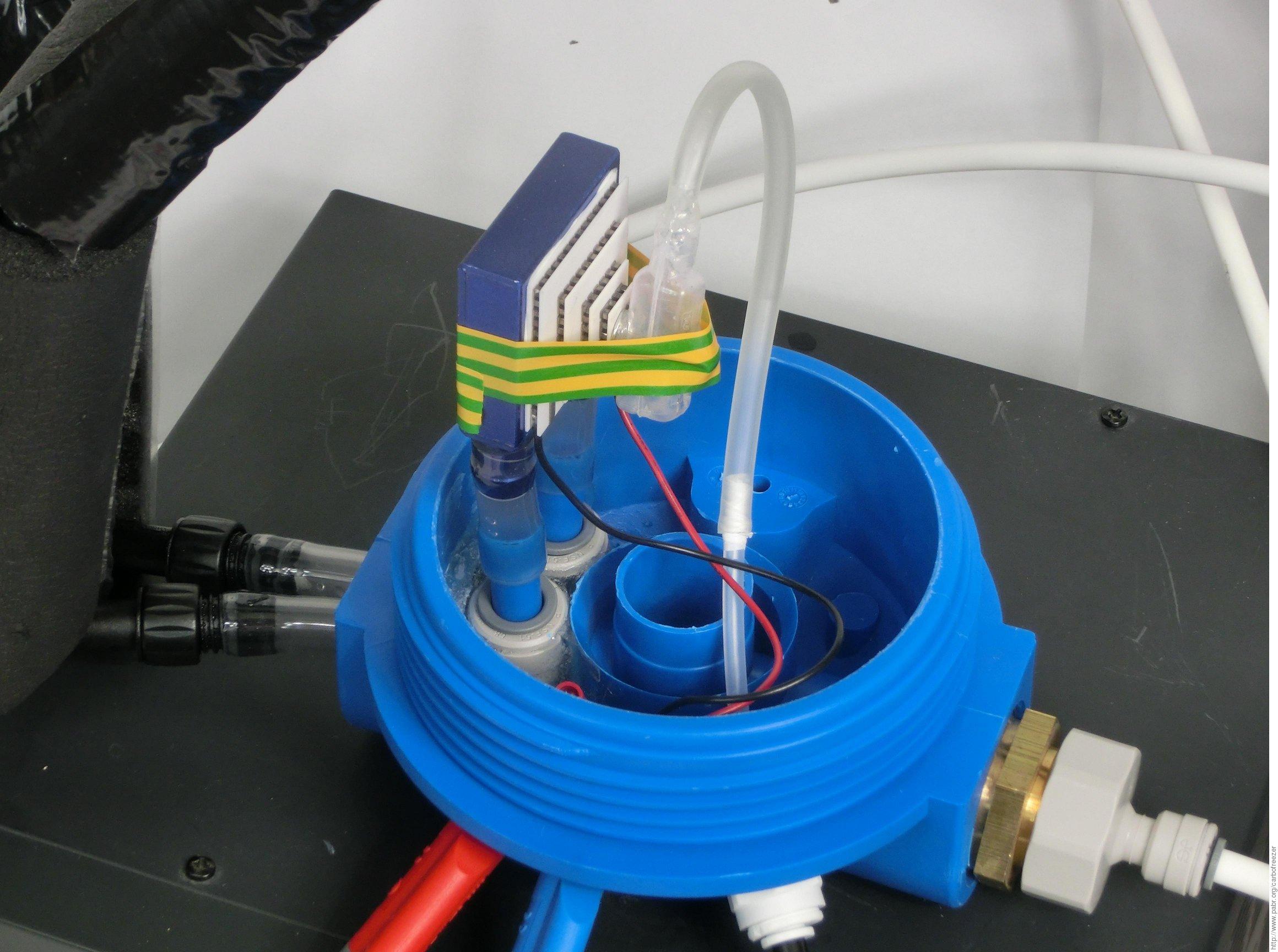
Next, CO2 was fed at atmospheric pressure into a small cell attached to the thermoelectric module. A 6 mm steel screw with flat/conical head serves as a cold finger.
Traces of white ice were observed between the threads of the screw, but the amount did not increase over the duration of the experiment, and it was not possible to determine whether this was dry ice or water ice.

Once/if dry ice is successfully produced, the following issues will have to be addressed:
How to collect the dry ice. Presumably no more than 100 .. 1000 mg can be kept near the Peltier module. Above a certain quantity and volume, thermal losses will exceed the cooling capacity.
How to store dry ice in such a way that it does not sublimate faster than it is produced. At atmospheric pressure this would require a container with excellent thermal insulation. An expensive Dewar flask reportedly vents 3 L of liquid nitrogen over 30 days; this suggests that 0.19 W leak into it at -196°C. Assuming the leakage is mostly by conduction at the neck rather than by radiation, it should drop to about 0.1 W at -80°C. This is the same order of magnitude as the expected cooling power of the Peltier module.
Alternatively, a non-insulated pressure-resistant container with a small mechanical airlock could be built. During each cycle of a 1 cm³ airlock, 100 mg of CO2 at 57 bar would be replaced with up to 1500 mg of dry ice.
At this point the project is an expensive failure. No amount of dry ice was conclusively produced. Plenty of tap water was wasted while operating the aspirator. Half a dozen cartridges of CO2 were vented into the atmosphere. The main satisfaction is that the improvised vacuum chamber has not imploded.
Possible reasons:
Maybe the cooling power budget is entirely exhausted by minute amounts of water vapour coming from the aspirator and condensing onto or inside the module. 0.1 W can freeze 9 mg/min of CO2 or 2 mg/min of water vapour.
Maybe the Peltier module is defective. It's hard to tell without a cryogenic thermometer.
The Peltier module has ratings for Th=50°C (where DTmax=126°C) and Th=27°C (where DTmax=112°C). In recognition that these specifications might be a bit optimistic, the module was operated with Th=5°C, even though Th=27°C should have been enough. But maybe the thermoelectric materials are not suitable for low temperatures anyway.
Maybe thermal radiation must be dealt with more carefully. Assuming black-body radiation, a 1 cm² load at -80°C receives 37 mW from an environment at 25°C.
Black-body radiation

| ! |    T |   Pout | Tenv |    Pin |        P |
|   | (°C) | (W/m²) | (°C) | (W/m²) | (mW/cm²) |
|---+------+--------+------+--------+----------|
| # |  -80 |    79. |   25 |   448. |      37. |
| # |  -80 |    79. |    0 |   316. |      24. |
| # | -196 |     2. |   25 |   448. |      45. |
#+TBLFM: $3=$stefan*(273.15+$T)^4;f0::$5=$stefan*(273.15+$Tenv)^4;f0::$6=($Pin-$Pout)*1e3/1e4;f0
#+CONSTANTS: stefan=5.67e-8
The thermal properties of the cold finger were not taken into account. Aluminium would have offered better conductivity and lower inertia than steel. Still, even under worst-case hypotheses, cool-down should take less than four minutes.
Cold finger

  S: Cross-section                                      Qcf: Cooling power at Tf
  L: Length                                             Toffs: Temperature gradient across cold finger
  d: Density                                            tcd: Cool-down time
  Cp: Heat capacity                                     T: Temperature of cold side
  K: Thermal conductivity
  Th: Temperature of hot side / initial temperature     Qc(T) = Qcmax.(1-(Th-T)/DTmax)  # Linear in datasheet
  Tf: Final temperature of cold side                    dt = (S.L.d.Cp).dT/Qc(T)
  Qcmax: Cooling power at T=Th                          dt = (S.L.d.Cp.Dtmax/Qcmax).(dT/DTmax)/(1-(Th-T)/DTmax)
  DTmax: Th-T when Qc=0                                 tcd = -(S.L.d.Cp.DTmax/Qcmax).ln(1-(Th-Tf)/DTmax)

| ! |   Th |   Tf |     S |    L |       d |       K |       Cp | Qcmax | DTmax |  Qcf | Toffs |  tcd |                |
|   | (°C) | (°C) | (mm²) | (mm) | (kg/m³) | (W/m/K) | (J/kg/K) |   (W) |   (K) |  (W) |   (K) |  (s) |                |
|---+------+------+-------+------+---------+---------+----------+-------+-------+------+-------+------+----------------|
| # |   27 |  -80 |    28 |   20 |    8000 |      43 |      450 |     4 |   112 | 0.18 |   3.0 | 176. | Steel          |
| # |    5 |  -80 |    28 |   20 |    8000 |      43 |      450 |     4 |   112 | 0.96 |  15.9 |  80. | +Water-cooling |
| # |    5 |  -80 |    28 |   20 |    8000 |      43 |      450 |     4 |    86 | 0.05 |   0.8 | 193. | +Derating      |
| # |    5 |  -80 |    28 |   20 |    2700 |     237 |      900 |     4 |    86 | 0.05 |   0.2 | 130. | Aluminium      |
#+TBLFM: $11=$Qcmax*(1-($Th-$Tf)/$DTmax);f2::$12=$Qcf/($K*($S*1e-6)/($L*1e-3));f1::$13=-($S*$L*1e-9*$d*$Cp*$DTmax/$Qcmax)*ln(1-($Th-$Tf)/$DTmax);f0
Obtain proper measuring equipment for cryogenic temperatures and low pressures.
Find out how manufacturers rate the performance of their thermoelectric modules.
Try multi-layer insulation instead of vacuum.
Surround the condensation cell with surfaces at 0°C to reduce thermal radiation.
Assemble six modules into a cubical box, leaving no room for radiative loss.
Some of the above sounds a lot like reinventing the Dewar flask. Maybe plugging a Peltier module into the cap of an off-the-shelf Dewar would be easier. Hopefully molecular gastronomy will expand the market for cryogenic containers and bring prices down.
Cool the hot side to -15°C with saturated saltwater.
Pressurize the condensation cell to 5 bar, just below the triple point of CO2. This would raise the sublimation temperature to -60°C.
[RDR2011] Comparison of Thermoelectric and Stirling Type Cryocoolers Using Control Thermodynamic Model . 2011. https://smartech.gatech.edu/bitstream/handle/1853/38793/041.pdf.