


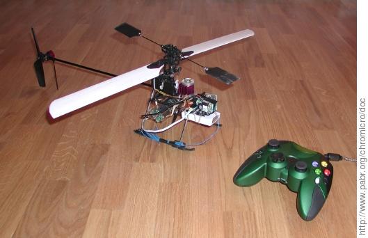
RC model helicopter prices have reached a point where all sorts of challenging (i.e. crash-prone) robotics projects become affordable. This document explains how to build a 300 g helicopter with embedded Linux and Bluetooth datalink from off-the shelf components for less than 500 EUR.
As a proof of concept, we provide software which allows the helicopter to be remotely controlled over Bluetooth with a PC joystick. Future work will focus on the integration of sensors (IMU, altitude, magnetic compas, GPS, camera) and flight control software (either third-party or dedicated).
Use these instructions and the related software at your own risk.
This is an experimental project with none of the fail-safe features one could expect in a commercial product.
Remote-controlled aircrafts are not toys. They are usually operated by properly-trained hobbyists on dedicated airfields, in compliance with any applicable regulations, with adequate liability insurance
Due to their mechanical complexity and large moving parts, helicopters are among the most dangerous aircrafts.
Experimental robotic aircrafts tend to wander in unpredictable ways. Ensure you have enough room.
Software dumps core. Hardware "crashes" (figuratively). Flying hardware crashes into the ground (or worse).
Lithium-polymer batteries are known to burst in flames when damaged or misused.
Bluetooth radio range is 10 m. This is not appropriate for outdoor remote-controlled flight.
Unlike 41/72 MHz R/C radio equipment, Bluetooth and Wi-Fi products use shared radio spectrum which can be jammed by various sources.


A number of inexpensive microhelicopters are now available to RC model hobbyists: Ikarus Piccolo, MS Hornet, Carboon, Dragonfly, Honeybee, Hummingbird, Tiny, Aerohawk, Blade CP, Sky Lark... These are essentially scaled-down versions of regular model helicopters, made possible by advances in battery technology. Some models have a rotor head with fixed collective pitch (FP), while others have both cyclic and collective variable pitch (CP). Most have a dedicated tail motor rather than a variable-pitch tail rotor.
A recent radical innovation is the "ProxFlyer" self-stabilizing deformable rotor design. Unfortunately, current commercial implementations are too small to carry mainstream sensors and embedded computers. However, due to its passive stability, this design will probably turn out to be the preferred choice for hovering robots which do not require high maneuverability.
Another alternative is the quad-rotor helicopter which is more silent, mechanically more robust, safer (with ducted rotors), and probably easier to control than a single-rotor/swashplate design. Potential weaknesses include: the overall size of the aircraft for a given payload, the energy efficiency of four small motors versus a larger one providing the same lift, and the impact of (usually fixed-pitch) rotors with high inertia on maneuverability.
For this project we use a microhelicopter kit containing:
A pre-assembled helicopter with variable-collective-pitch rotor, two brushed motors and three miniature servos
An "all-in-one" controller package with BEC, 6-channel RC receiver, yaw gyro, and ESCs
A 41 MHz 6-channel RC transmitter with hardwired CCPM mixing
A 11.1 V lithium-polymer battery
A battery charger.
The aircraft has a mass of 270 g and can lift about 50 g of payload.
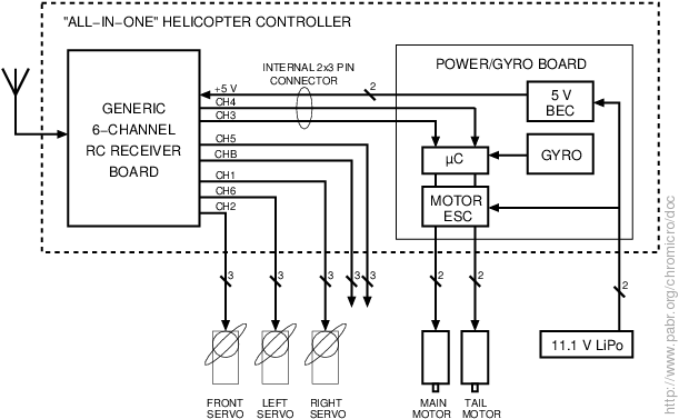
An "all-in-one" controller package connects all the components together. This is in contrast with larger model helicopters, where the connections between the receiver, gyro, BEC and ESCs are exposed and documented. Integrating all these functions reduces size, weight and cost, but makes modifications harder.
Fortunately, in some commercial microhelicopters, the "all-in-one" controller can be tinkered with fairly easily. It actually consists of two boards connected back-to-back with a 2x3-pin connector (see Figure 1, “ Contents of the integrated controller in a typical commercial microhelicopter kit ”):
A generic RC receiver board with seven 3-pin PWM servo outputs.
A power/gyro board with BEC, gyro, fail-safe, and ESCs.
Table 1, “ RC receiver PWM outputs ” lists the PWM outputs of the receiver board, two of which are routed internally to the power/gyro board.
Table 1. RC receiver PWM outputs
| Channel | Usage |
|---|---|
| 1 | Right servo |
| 2 | Front servo |
| 3 | Main motor (internally connected to the power/gyro board) |
| 4 | Tail rotor (internally connected to the power/gyro board) |
| 5 | Unused |
| 6 | Left servo |
| B | Unused (12 ms sync pulses) |
Any similar helicopter can be used. The main requirements are:
The controller board must use PWM signals. Generating PCM signals would require more work, especially if proprietary encodings are used.
The controller board must expose the multiplexed PPM signal between the FM radio receiver and the demultiplexer (see Section 4.2, “ PWM injection mod ”), or at least the PWM inputs to the motor ESCs. It must accept 3.3 V signals.
The helicopter must be strong enough to lift at least 30 g of payload.
The battery must be able to supply 200 mA of additional current.
We use a Gumstix single-board computer with the following features:
200 MHz XScale PXA255 processor (ARM core plus I/O functions)
4 MiB flash with factory-installed Linux-2.6.10 and utilities
64 MiB SDRAM
General-purpose I/O pins
I/O daughterboard with 2.54 mm pads
I2C bus
Bluetooth module and antenna
Comprehensive software development environment.
Some features are not used:
Dual channel hardware PWM generator: Intended for driving the brightness and contrast of a LCD display. Eventually we will need more than two channels.
USB client interface: Intended for PXA255-based PDAs. usbnet is convenient for logging into the board, but we can use Bluetooth instead.
Gyros (which measure angular rate of rotation) are commonly used in RC model helicopters. MEMS accelerometers are now routinely found in mass-market devices such as camcorders, hard disks and cars. Accelerometers can also be used as inclinometers in stationary applications.
The power/gyro board has two +5 V voltage regulators labelled CX1117-5.0 and mounted in parallel. Current is 50 mA when idle and ranges from 3 to 5 A while flying.
Since this +5 V rail is exposed on each servo connector (including the unused ones), the CPU board can be conveniently powered from it. In order to accomodate the extra current (100 to 200 mA), it might be necessary to replace the two voltage regulators with a larger, externally-mounted regulator.
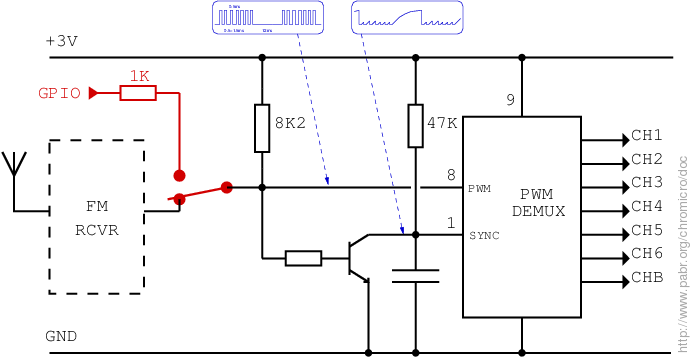
In order to control the helicopter, we modify the RC receiver board so that the board can inject its own PPM signal into the PPM demultiplexer.
Why not get rid of the receiver board entirely and generate five PWM signals with the CPU board ? . The proposed approach has several advantages:
No need to build a custom PCB.
Only three wires between the CPU board and the original controller: GND, +5 V, and one multiplexed PPM signal .
The PPM demultiplexer adds one layer of electrical isolation between the CPU board and the power circuits.
Figure 2, “ RC receiver board details and modifications (in red) ” shows details of a typical RC receiver board and the modification. Simply cut the correct PCB trace(s) and connect both ends to a 2-pin connector outside of the plastic enclosure. Chronograms should help locate the signals.
This modification can be done in such a way that the original functionality is restored simply by disconnecting the CPU board and inserting a jumper.
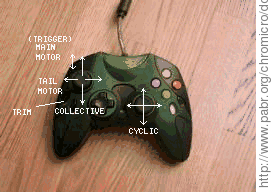
Xbox controllers are widely available, inexpensive, and have well-defined functionality (unlike PC joysticks). They can be connected to a PC by replacing the proprietary connector with a USB type A plug. Just connect the four wires with matching colors and ignore the extra yellow wire.
Alternatively, any USB joystick (a.k.a. joypad or gamepad) with two dual-axis analog sticks can be used. In this case the mixer configuration file must be adjusted to match the layout of the axes (see iprc_tx in [PXARC]).
The software developed for this project is now packaged separately. See [PXARC].
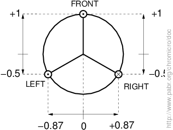
Depending on the type of helicopter used,
it might be necessary to configure iprc_tx to perform the CCPM mixing.
An example can be found in Figure 3, “
Mixer configuration xpad_ccpm120_mode2.mix.
”.
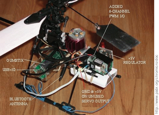
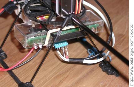
Figure 6, “ Rear view with connector on I/O daughterboard. ” and Table 2, “ I/O daughterboard pin assignments. ” show the connection with the Gumstix daughterboard.
Table 2. I/O daughterboard pin assignments.
| Pin | Signal | Usage |
|---|---|---|
| 10 | NACRESET (disconnected by cutting the trace on the PCB) | +5 V CC in |
| 16 | GND | GND |
| 18 | GPIO61 | 6-channel PWM out |
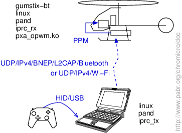
In this scenario (Figure 7, “ Remote control over Bluetooth or Wi-Fi ”) we simply emulate a regular remote control. There are no sensors on the helicopter, no complex embedded software, and no feedback from the helicopter to the ground station.
Procedure 1. Startup
Start iprc_tx on the PC.
Connect the battery. The GPIO pin will be pulled high while the processor is booting.
Setup networking over Bluetooth (BNEP). This can be automated with the daemon pand.
Load the pxa_opwm module. The GPIO pin will be configured for output, but kept at logic 0 level.
Start iprc_rx on the embedded board. PPM will be generated as soon as UDP packets are received.
Procedure 2. Shutdown
Either disconnect the battery, stop iprc_rx, or stop iprc_tx. All alternatives should be equally safe. Note that with the original remote control, it is mandatory to shutdown the receiver or disconnect the battery before stopping the transmitter.
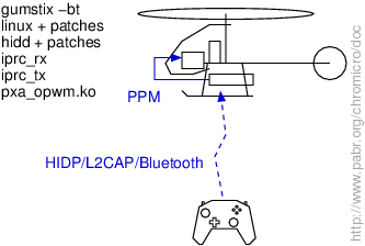
In this variant (Figure 8, “ Remote control with a Bluetooth joystick ”) we take advantage of the fact that some modern wireless joysticks are compatible with the Bluetooth HID Profile, and can therefore connect directly to the on-board Linux computer with Bluetooth module. Instructions for using the PS3 "SIXAXIS" controller can be found in [SIXLINUX].
Inertial measurement unit. 6 DoF, I2C interface.
Digital video camera
Magnetometer (compas). I2C interface.
Pressure (altitude, airspeed). I2C interface.
[PXA255_ELEC] Intel PXA255 Processor. Electrical, Mechanical, and Thermal Specification. 27878002.pdf.
[PXARC] pxaRC - R/C and robotics software for Linux/PXA255/PXA270 . http://www.pabr.org/pxarc/doc/pxarc.en.html .
[SIXLINUX] Using the PlayStation 3 controller in Bluetooth mode with Linux . http://www.pabr.org/sixlinux/sixlinux.en.html .
- Battery-Elimination Circuit (BEC)
A DC-DC voltage converter (linear regulator or switching converter) which is used to power a RC receiver and servos from the same battery as the motors. Output is typically 4.8 V or 5 V.
- Bluetooth Network Encapsulation Protocol (BNEP)
Provides an ethernet-like interface (e.g. bnep0) at each end of a Bluetooth connection.
- Collective pitch helicopter (CP)
Refers to a helicopter rotor design with variable collective pitch. Thrust is controlled by varying either the collective pitch or the speed of the main motor, or both.
See Also Fixed pitch helicopter.
- Cyclic-Collective Pitch Mixing (CCPM)
- Duty Cycle Modulation (DCM)
A modulation which encodes an analog signal into the average value of a square-wave signal. Typically used to drive an electric motor with an H-bridge.
See Also Pulse Width Modulation.
- Drone
See Also Unmanned Aerial Vehicle.
- Electronic Speed Controller (ESC)
A motor speed controller, typically driven by a PWM signal in RC models.
- Fixed pitch helicopter (FP)
Refers to a helicopter rotor design with cyclic pitch, but fixed collective pitch. Thrust is controlled by varying the speed of the main motor. This causes more inertia than in a "CP" helicopter. Besides, "FP" helicopters cannot fly inverted.
See Also Collective pitch helicopter .
- General-Purpose I/O (GPIO)
The PXA255 has 85 general-purpose pins which can be independently configured for input or output, or connected to integrated peripheral functions (e.g. serial ports and LCD driver).
- Global Positioning System (GPS)
- Inertial Measurement Unit (IMU)
Accelerometers (translation) and gyros (rotation).
- Lithium-Polymer (LiPo)
- Mode 1 / Mode 2
Most popular layouts for axes on a RC helicopter transmitter.
- Printed Circuit Board (PCB)
- Pulse Code Modulation (PCM)
Refers to a digital transmission, in contrast with PWM or PPM.
See Also Pulse Width Modulation, Pulse Position Modulation.
- Pulse Position Modulation (PPM)
Refers to a multiple-channel differential PPM signal, in RC terminology.
See Also Pulse Width Modulation, Pulse Code Modulation.
- Pulse Width Modulation (PWM)
A modulation which encodes an analog signal into variable-duration digital pulses. Typically used to drive RC servos.
See Also Pulse Position Modulation, Duty Cycle Modulation.
- Unmanned Aerial Vehicle (UAV)
Note: An unmanned vehicle is not necessarily autonomous.
See Also Drone.