


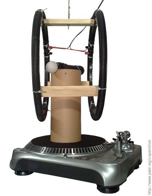


In this project we follow in the footsteps of Léon Foucault who in 1851 produced the first convincing experimental evidence of Earth's diurnal rotation, thus confirming a crucial element of the heliocentric model of the solar system. For lack of a 28 kg pendulum and a 70-meter-high ceiling to suspend it from, we use a table-top apparatus whose main components are a PlayStation Move motion-sensing videogame controller and a 33/45 RPM record player.
With an acquisition time of several hours, our device has little practical use, but this is an enlightening physics experiment that anyone can easily replicate. Technical details and source code are provided. Readers who prefer to skip the hardware tinkering phase will find raw datasets as well.
According to our review (see Appendix A, Historical context ), all earlier experimental confirmations of Earth's rotation required expensive or dedicated, carefully crafted instruments - including the pendulum, despite its apparent simplicity. With a few improvements (see Section 8, “ Perspectives ”), our approach will allow millions of individuals to confirm Earth's rotation for themselves at negligible cost and effort, without advanced technical skills, using only household items - a democratization of the Copernican revolution made possible by the consumer electronic industry.
This project was developed independently and is not endorsed by any third party. Claims of performance contained in this article are derived from our own tests and measurements on specific units only.
The PS Move is marketed as a peripheral with Bluetooth connectivity (Bluetooth is an open standard which promotes interoperability between computers and wireless devices), and we believe this experiment uses it exactly as intended (as a motion-sensing peripheral). There is no need to modify the device or circumvent any protection. Still, following these instructions might void your warranty, damage your hardware, or worse. Use at your own risk !
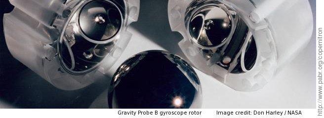
Gyroscopes used to be synonymous with sophisticated navigation systems for aircrafts, nuclear submarines, rockets and ballistic missiles.
In recent years, thanks to the industrial-scale production of microelectromechanical systems, they have become ubiquitous. MEMS gyroscopes can now be found in millions of video cameras, GPS receivers, mobile phones and videogame controllers.
Due to their principle of operation, gyroscopes measure their rate of rotation, not with respect to the ground, but with respect to an inertial frame of reference aligned with the distant stars. Since the Earth itself rotates with respect to the celestial sphere, a stationary MEMS gyroscope will sense that rotation.
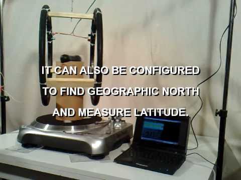
For mainstream applications whose purpose is to track the orientation of a vehicle or hand-held device with respect to the ground, Earth's rotation is merely a source of small measurement errors. However, there are industrial applications for devices sensitive enough to detect it. By measuring not just the rate of rotation but also the direction of its axis, one can determine true north (also known as geographic north) and latitude. The gyrocompass has become a crucial instrument in environments where neither the night sky nor Earth's magnetic field can be observed reliably, such as underseas (submarine navigation) and underground (drilling, pipe mapping). Unlike the directional gyroscope, the gyrocompass does not require manual initialization and does not drift.
Sophisticated devices are used for such applications. It was unclear, when we started this project, whether inexpensive consumer-grade MEMS gyroscopes could detect Earth's rotation, be it only qualitatively.


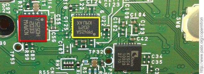
According to [IFIXIT], the gyroscope in the PS MOVE is a chip labeled Y5250H. We found this suspicious because the marking is reminiscent of a single-axis yaw gyroscope from ST (presumably a custom variant of their LY5150ALH) whereas the PS Move is known to measure rotations on all three axes. We disassembled our unit and discovered a slightly different board layout, with an additional dual-axis ST PR425A gyroscope where IFIXIT had photographed an unidentifiable shielded device.
From earlier experiments (see [LINMCTOOL]), we know that the PS Move is a regular Bluetooth-compliant peripheral, and that its designers were kind enough not to add any obfuscation or encryption on top of the standard. As a result, sensor data can be retrieved by any Bluetooth-enabled computer. Data is transmitted wirelessly as Bluetooth HID reports.
Gyroscope data transmitted over Bluetooth suggests a sampling rate of about 176 Hz with a full scale range of about ±3000 °/s and a dynamic range of 16 bits, providing a resolution of 0.09 °/s. This is most likely achieved by oversampling since internal hardware details imply that six analog sensors are multiplexed toward two ADCs capable of 12 bits at up to 1 MHz each. Measurements from a stationary gyroscope has a standard deviation of about 0.45 °/s, which translates to a noise density of 0.05 °/s/√Hz, consistent with the state of the art in consumer-grade MEMS gyroscopes.
The Earth rotates 360 ° in one sidereal day of 23 h 56 min 4 s, i.e. at a rate of 0.0042 °/s. This is 20 times smaller than the gyroscope resolution and well below the noise floor. Obviously, some post-processing of the gyroscope data will be required.
Under the usual assumptions about measurement noise, we should be able to measure Earth's rotation with acceptable uncertainty simply by averaging a few million samples from a stationary gyroscope aligned in the north-south direction. The resulting value would reflect Earth's rotation plus an unwanted offset called the zero-rate bias. We would subtract that offset after estimating it by performing a second measurement with the same gyroscope aligned east-west (where it is not affected by Earth's rotation).
Unfortunately the zero-rate bias of a gyroscope cannot be calibrated out so easily because it tends to drift slowly and unpredictably. Bias stability is a crucial parameter of the performance of a gyroscope. For obvious reasons, devices with excellent bias stability are even classified as weapons components under ITAR.
With inexpensive consumer-grade MEMS gyroscopes, the bias drifts within minutes. Therefore we cannot expect consistent results across successive measurements lasting several hours each.
In [MST2005], a stepper motor mechanically toggles the orientation of a gyroscope back and forth 180 ° every 1.8 s, and the gyroscope is sampled at rest for a fraction of a second at each extremal orientation. The bias value remains stable over such short time scales. Thus, it is effectively removed by subtracting one set of measurements from the other.
[BMR] analyzes the benefits of slewing gyroscopes and accelerometers in sophisticated patterns with two degrees of freedom.
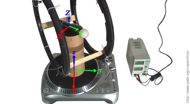
Our approach is similar. Instead of building a custom motorized mount and control system, we spin a gyroscope continuously on an off-the-shelf vinyl record player.
From a signal processing perspective, we modulate the signal of interest mechanically so as to shift it out of a noisy part of the spectrum, and then we demodulate at the same frequency with the software equivalent of a lock-in amplifier. When applicable, this is a popular technique for dealing with non-uniform noise spectra, and with low frequency noise in particular.
The output of the demodulator is a complex number which provides both the rate of Earth's rotation (multiplied by the cosine of latitude) and the direction of its axis with respect to the phase origin of the modulation.

Record players are useful as amateur scientific instruments because audiophiles tend to have high expectations regarding mechanical construction, speed accuracy and stability, vibrations, magnetic shielding of motors, etc.
For our first attempt we used the least expensive unit we could find, a belt-driven model. After measuring a rotation rate of 46 RPM instead of 45, we concluded that it did not even have a crystal-controlled synchronous motor, and we upgraded to an entry-level direct-drive model (130 EUR retail). The direct-drive unit proved satisfactory.
Since we had to implement robust synchronization mechanisms in software eventually, a precise turntable does not appear to be a crucial requirement anymore, and we encourage readers to try and replicate the experiment with any unit they may have access to.
The PS Move is mounted on the platter in its natural orientation. Either the X-axis (pitch) or the Y-axis (roll) gyroscope can be used to sense Earth's rotation.
Early versions of our apparatus failed to produce conclusive results. It took some time to discover that gyroscope measurements were being affected by Earth's weak magnetic field. This was confirmed by measuring the response of a stationary gyroscope to a permanent magnet spinning nearby.
We found no mention of such an effect in publications about MEMS gyroscopes. Actually, magnetic fields could be affecting not the MEMS sensors themselves, but the associated electronic circuitry.

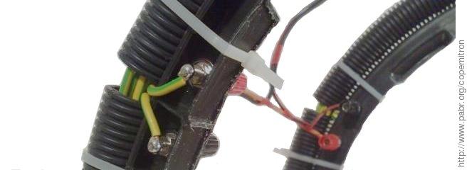
Magnetic shielding might help address this issue, but mu-metal is hard to procure and would interfere with Bluetooth communications. Instead we use a Helmholtz coil to cancel Earth's magnetic field in the vicinity of the gyroscope. We spent more time than necessary building this coil; a crude version could be made by wrapping electrical wire around a cardboard box.
The PS Move, the host computer and the turntable each have their own clock, and we have no direct way of synchronizing them.
The host computer is synchronized to a global time reference via NTP. But since the operating system and Bluetooth communication stack introduce unpredictable latency, high resolution time-stamping of incoming packets has little value. We only take advantage of NTP synchronization to accurately measure sampling rates and rotation rates over long periods (several hours).
The reporting rate of the PS Move seems to be slightly affected by temperature (at least 20 ppm/K in one of our tests). Samples are transmitted with what looks like a time-stamp field, but we could not find a use for it and we simply assumed that the sensors are sampled at regular intervals. The sequence number field allows detection of packet loss on the wireless link.
The turntable appears to have a precise and stable rotation rate, but this is not good enough to keep it in-phase with the computer over several hours.
Thus, a crucial component of our homodyne signal processing is a phase-locked loop which synchronizes the software-based demodulator with the mechanical modulation performed by the turntable.
In our current implementation, the PLL is simply derived from another sensor of the PS Move, with narrow-band filtering around 0.56 or 0.75 Hz. If a magnetometer is used as reference, the PLL will be aligned with the local residual magnetic field. (Despite the action of the Helmholtz coil, the magnetometers detect Earth's field because they spin 80 mm off-axis.) If an accelerometer is used as reference, the PLL can be aligned in a specific direction by deliberately tilting the turntable.
Being mechanical devices with vibrating structures, MEMS gyroscopes tend to respond not only to rotation rates, but also to linear accelerations. Manufacturers know how to mitigate this with pairs of counterbalanced proof masses, and any residual effect is small enough to not even be mentioned in datasheets of gyroscopes marketed for mainstream applications. However, even aircraft-grade gyroscopes claim sensitivities as high as 0.05 °/s/g. This implies that a linear acceleration of only 0.08 g may cause an unwanted response as large as Earth's rotation's.
In our apparatus, the gyroscope experiences linear accelerations from gravity and from the rotational motion of the turntable. We carefully align the rotation axis of the turntable vertically. Hence, in the rotating frame of reference, gravity and centrifugal forces are stationary, and we hope that their effect is cancelled by the homodyning process.
The rotation of the turntable will be sensed by any gyroscope whose axis is not perfectly orthogonal to that of the turntable. The effects of its DC component and random fluctuations will be cancelled by the homodyning process, but any synchronous fluctuation will directly affect the final result. Synchronous fluctuations may be caused by:
friction in the turntable bearings
an unbalanced payload spinning around a non-vertical rotation axis
inhomogeneous stiffness of rubber belts or similar components
the switched nature of magnetic forces in the motor.
In Figure 10, “ Fluctuation of turntable rotation rate ” the 16th-harmonic fluctuation strongly suggests that the motor has 16 magnetic poles. The fundamental component of about 1000 ppm is a more serious concern. We have not determined its cause.
It should be possible to damp fluctuations mechanically with a flywheel attached to the platter via flexible mounts, but our attempts with household materials proved unsuccessful. We also tried to estimate the relative amplitude of fluctuations and subtract their predicted impact on the demodulated output, with limited success.
Eventually we chose to reduce the effect of fluctuations as much as possible by carefully aligning the gyroscope axis with the rotation plane.The coil is aligned with the horizontal component of Earth's magnetic field. The vertical component needs not be cancelled because it is stationary in the vicinity of the gyroscope, at the center of the rotating frame.
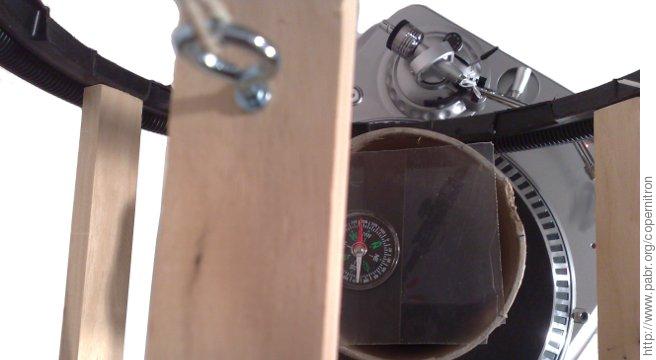
The sensing gyroscope is located 22 mm behind the "PS" button, in the upper half of the device. It must spin at the center of the coil.
Any inclination of the turntable with respect to the horizontal plane causes gravity in the rotating frame of reference to wobble in a way that can be measured by the accelerometers of the PS Move, using the homodyning technique again. Repeatability is better than 0.05 °; a rigorous estimation of accuracy has not been carried out.
Any inclination is corrected manually by inserting strips of paper (about 100 µm thick) under the feet of the turntable.
To ensure that the sensing gyroscope is orthogonal to the axis of the turntable, we simply measure its response to the rotation of the turntable (ideally, it should be zero). This is done by averaging the signal and subtracting the zero-rate bias, all within one minute. Repeatability is better than 0.05 °, but we do not make any claim about accuracy here either.
linmctool (see [LINMCTOOL]) receives data from the PS Move:
# wget http://www.pabr.org/linmctool/linmctool-20110206.c
# gcc --std=gnu99 -Wall linmctool-20110206.c -lusb -o linmctool
# ./linmctool --timestamp  |  bzip2  > data.dat.bz2
copernitron-20110210.m is a script for GNU Octave / MATLAB with the following minimal functionality:
Parsing data files recorded by linmctool.
Homodyne demodulation synchronized with the X- and Y-axis magnetometers.
Estimation of alignment errors between the turntable and the horizontal plane.
Simplified estimation of alignment errors between the PS Move and the rotating platter.
Estimation of the residual magnetic field. This actually reflects the radial and tangential components of the field on a circumference about 80 mm from the axis, not the field that the gyroscopes experience.
Measurement of Earth's rotation rate, in rotations per sidereal day, with a confidence interval accounting for sensor noise and gyroscope alignment errors.
Estimation of the direction of true north with respect to the residual magnetic field (which might differ from magnetic north).
The figures below show measurements of the rate and direction of Earth's rotation obtained from each dataset and each horizontal gyroscope (gX and gY). The demodulator outputs a complex number which we normalize to the expected value (blue circle: one rotation per sidereal day) and display with the PLL phase origin up. Note that error margins (green and red circles) account for known effects only: sensor noise and gyroscope alignment errors.
Even with 17 hour long recordings, the process is not entirely reliable. Unfortunately we cannot perform a control experiment with Earth's rotation switched off and all other things equal; but several facts suggest that the signal actually reflects Earth's rotation rather than experimental artifacts or other directional phenomena:
The two horizontal gyroscopes, gX and gY, provide two independent results from each dataset. We can check whether the two results are in agreement (up to error margins and a 90 ° phase difference).
Repeatability is tested by processing independent fragments of each dataset (green circles).
We can slightly alter the alignment of the turntable with the horizontal plane and with the gyroscope and verify that the demodulated signal still points toward the same azimuth.
Similarly, we can rotate the chassis of the turntable by 90 ° to ensure that the signal does not reflect a preferential direction of mechanical friction.
Across all datasets, even with poor alignment and large residual magnetic fields, the measured rotation rate is within ±50 % of the expected value.
Each dataset is about 100 MB. To download, please change the URL extension to ".dat.bz2".
stationary-magnet-off.dat. This is 11 hours of noise from a stationary device.
dd45eeehelm.dat. The X-axis gyroscope is poorly aligned; the Y-axis gyroscope yields a reasonable margin of error.
dataset = dd45eeehelm
latitude =  48
rpm_nominal =  45
count =  9894401
duration =  5.5933e+04
Sample rate: 176.898 Hz (ignoring packet loss).
mX: Residual mag. north 2.3 µT at -0 ° CW from PLL origin.
mY: Residual mag. north 2.3 µT at 1 ° CW from PLL origin.
aX: Turntable tilt 0.011 ° up at 78 ° CW from PLL origin.
aY: Turntable tilt 0.013 ° up at 72 ° CW from PLL origin.
Rate fluctuation: 1057 ppm.
Using gyro gX.
  Range: 12.175 °/s  mean: -0.637 °/s  stddev: 0.474 °/s.
  Tilt: 0.135 ± 0.021 °.
  Earth rotation rate: 0.668 rotations per sidereal day
                      ±0.309 with 95% confidence.
  True north: -10.4 ° clockwise from PLL origin.
Using gyro gY.
  Range: 15.219 °/s  mean: 0.005 °/s  stddev: 0.406 °/s.
  Tilt: -0.001 ± 0.021 °.
  Earth rotation rate: 0.859 rotations per sidereal day
                      ±0.105 with 95% confidence.
  True north: 31.5 ° clockwise from PLL origin.
dd33alignedB.dat. The coil current is deliberately set slightly higher than needed (530 mA) in order to confirm that the experiment detects the direction of true north, rather than that of the local magnetic field via unintended effects.
dataset = dd33alignedB
latitude =  48
rpm_nominal =  33.333
count =  9894401
duration =  5.6350e+04
Sample rate: 175.589 Hz (ignoring packet loss).
mX: Residual mag. north 2.0 µT at -1 ° CW from PLL origin.
mY: Residual mag. north 2.0 µT at 1 ° CW from PLL origin.
aX: Turntable tilt 0.006 ° up at 53 ° CW from PLL origin.
aY: Turntable tilt 0.006 ° up at 65 ° CW from PLL origin.
Rate fluctuation: 1008 ppm.
Using gyro gX.
  Range: 4.834 °/s  mean: -0.535 °/s  stddev: 0.474 °/s.
  Tilt: 0.153 ± 0.029 °.
  Earth rotation rate: 0.750 rotations per sidereal day
                      ±0.269 with 95% confidence.
  True north: -144.7 ° clockwise from PLL origin.
Using gyro gY.
  Range: 4.566 °/s  mean: 0.258 °/s  stddev: 0.386 °/s.
  Tilt: -0.074 ± 0.029 °.
  Earth rotation rate: 0.547 rotations per sidereal day
                      ±0.173 with 95% confidence.
  True north: -137.2 ° clockwise from PLL origin.
dd45aligned.dat. The turntable and sensors are carefully aligned. We suspect that natural fluctuations of Earth's magnetic field make the direction of the residual field unstable, yielding an unreliable PLL.
dataset = dd45aligned
latitude =  48
rpm_nominal =  45
count =  9894401
duration =  5.6344e+04
Sample rate: 175.607 Hz (ignoring packet loss).
mX: Residual mag. north 0.9 µT at -1 ° CW from PLL origin.
mY: Residual mag. north 0.9 µT at -1 ° CW from PLL origin.
aX: Turntable tilt 0.002 ° up at 93 ° CW from PLL origin.
aY: Turntable tilt 0.003 ° up at 147 ° CW from PLL origin.
Rate fluctuation: 1049 ppm.
Using gyro gX.
  Range: 4.745 °/s  mean: -0.629 °/s  stddev: 0.460 °/s.
  Tilt: 0.133 ± 0.021 °.
  Earth rotation rate: 0.771 rotations per sidereal day
                      ±0.302 with 95% confidence.
  True north: -74.4 ° clockwise from PLL origin.
Using gyro gY.
  Range: 4.029 °/s  mean: 0.333 °/s  stddev: 0.381 °/s.
  Tilt: -0.071 ± 0.021 °.
  Earth rotation rate: 0.521 rotations per sidereal day
                      ±0.199 with 95% confidence.
  True north: -68.9 ° clockwise from PLL origin.
dd45tiltup115.dat. The turntable is deliberately tilted up toward azimuth 115 °E in order to locate true north with respect to a known direction. This tilt seems to affect phase measurements in a way that is not understood yet.
dataset = dd45tiltup115
latitude =  48
rpm_nominal =  45
count =  8199671
duration =  4.6695e+04
Sample rate: 175.602 Hz (ignoring packet loss).
*** PLL TILT ***
mX: Residual mag. north 1.1 µT at -39 ° CW from PLL origin.
mY: Residual mag. north 1.0 µT at -40 ° CW from PLL origin.
aX: Turntable tilt 0.065 ° up at -1 ° CW from PLL origin.
aY: Turntable tilt 0.062 ° up at 1 ° CW from PLL origin.
Rate fluctuation: 1013 ppm.
Using gyro gX.
  Range: 4.834 °/s  mean: -0.310 °/s  stddev: 0.476 °/s.
  Tilt: 0.066 ± 0.021 °.
  Earth rotation rate: 1.225 rotations per sidereal day
                      ±0.214 with 95% confidence.
  True north: -167.7 ° clockwise from PLL origin.
Using gyro gY.
  Range: 4.029 °/s  mean: 0.190 °/s  stddev: 0.374 °/s.
  Tilt: -0.040 ± 0.021 °.
  Earth rotation rate: 0.884 rotations per sidereal day
                      ±0.158 with 95% confidence.
  True north: -60.8 ° clockwise from PLL origin.
Hardware improvements . Our experiments are typically started in the evening and left to run for up to 17 hours. The PS Move is attached to a cardboard column with rubber bands, and the rubber feet of the turntable stand on a wooden table. All of these materials may expand or contract in response to changes in ambient temperature or humidity. Mechanical alignments could be improved with more suitable materials.
Mechanical modelling of vibrating MEMS gyroscopes . We implicitly assumed that our gyroscopes respond instantaneously to variations of the rate and direction of their rotation, ignoring the action of the Euler force on the vibrating structure. We also ignored the impact of fluctuating linear accelerations. On the one hand, this is not unreasonable because MEMS gyroscopes typically vibrate at frequencies three or four orders of magnitude higher than that of the turntable. On the other hand, homodyne demodulation might be sensitive enough to detect periodic dynamic effects. A better model could improve results and explain the anomalies in Figure 15, “ dd45tiltup115.dat. Azimuth 115 °E is up. ”.
Binary modulation instead of continuous rotation . For this project, a major challenge was to require only household items and minimize construction work. This led to using a game controller, a turntable, and harmonic modulation of the signal of interest. But the approach of [MST2005], where the gyroscope is sampled at rest in two opposite orientations, avoids many of the complications of continuous rotation. Readers are encouraged to devise mechanical contraption made from common items which would achieve suitable motions (crank and connecting rod ? windshield wiper motor ? LEGO ?). Note that the motor needs not be controlled by the computer: we can use the magnetometers to trigger sampling whenever the gyroscope reaches a proper orientation.
Modelling the effect of magnetic fields . The Helmholtz coil is the only component in our device which requires some hardware tinkering, and this detracts from the simplicity of the project. Magnetic shielding should be investigated. As an alternative, it might be possible to understand and model how magnetic fields affect measurements and use that knowledge to cancel their effect in software.
Unknown preprocessing ? . What we considered as raw sensor data throughout this article might actually be preprocessed in undocumented ways inside the PS Move. For example, we noticed a peak at 88 Hz in the noise spectrum. This suggests that the two samples in each Bluetooth packet are processed differently.
Measuring latitude . Latitude can be derived from the known value of Earth's rotation rate and a local measurement of its horizontal component. Alternatively, we could spin a gyroscope in a vertical meridian plane.
Multiple models of the PS Move ? . As mentioned in Section 4, “ Back-of-the-envelope calculations ”, there are at least two versions of PS Move hardware (redesigns are routine throughout the lifetime of industrial products). On the one hand, we cannot guarantee that the experiment will work with versions other than CECH-ZCM1E; On the other hand, it might actually work better with those which have built-in magnetic shielding around the gyroscope.
Other devices with gyroscopes . As far as we know the PS Move has the gyroscopes with the highest dynamic range (16 bits) in its market segment. But it also has an unusually wide full scale range (±3000 °/s), which is excellent for motion tracking, but suboptimal for our project. Many MEMS gyroscopes have a secondary "amplified" analog output with a reduced range. According to [WIIBREW], the Wii MotionPlus has gyroscopes with only 14 bit dynamic range, but it does support a "slow" mode with a narrow range. Therefore it should be able to detect Earth's rotation with comparable performance. If it were discovered that the gyroscopes of the PS Move can be configured to operate with a narrower range too, acquisition time might be reduced.
Mobile app . We are investigating whether the gyroscopes found in mobile phones are suitable for this experiment.
Detect tidal forces ? . Both the Moon and the Sun cause gravity at Earth's surface to fluctuate by about 0.1 ppm. One could attempt to detect this effect with inertial MEMS sensors, using similar techniques.
[LINMCTOOL] linmctool - Linux motion-sensing controller tool . http://www.pabr.org/linmctool/linmctool.en.html .
[IFIXIT] PlayStation Move Teardown. http://www.ifixit.com/Teardown/PlayStation-Move-Teardown/3594/2#s17213.
[WIIBREW] Wiimote/Extension Controllers. http://wiibrew.org/wiki/Wiimote/Extension_Controllers#Wii_Motion_Plus.
[MST2005] Earth rotation measurement with micro-mechanical yaw-rate gyro. Measurement Science and Technology. 11. November 2005 . http://iopscience.iop.org/0957-0233/16/11/024/. http://didel.script.univ-paris-diderot.fr/claroline/backends/download.php?url=L0FyY2hpdi9FeHBvc%2BlzL2VhcnRoX3JvdGF0aW9uX3NlbnMucGRm&cidReset=true&cidReq=36UAHB543.
[BMR] The effect of carouseling on MEMS IMU performance for gyrocompassing applications. Massachusetts Institute of Technology2009. http://dspace.mit.edu/handle/1721.1/51645.
A. Historical context
The search for experimental proofs (or refutations) of Earth's rotation is a major connecting thread throughout the beginning of the modern age. As often happens in the history of scientific discoveries, we tend to focus on a specific event (one day, one place, one individual) and praise it as a crucial turning point. In the case at hand, that would be Léon Foucault's public exhibition of his tallest pendulum under the dome of the Panthéon in 1851. But historians expose a more colourful and protracted timeline. We recommend reading [RIGGE] (available online) or its primary sources [GILBERT] and [HAGEN] (in French).
Some of Foucault's predecessors designed suitable experiments, but often lacked the technology required to reliably execute them. Others reported conclusive experimental results, but today's experts retroactively estimate that, given the technical know-how of their era, they cannot possibly have achieved an adequate margin of error. Yet others did notice actual effects of Earth's rotation in unrelated experiments, but dismissed them as annoying artifacts.
Note . [HAGEN], [GILBERT] and [RIGGE] all write about "proofs" of Earth's rotation. A proof is a mathematical concept which only makes sense in a specific model, which in the 19th century was implicitly Newton's laws of motion. In the early 20th century, the concept of inertial frame of reference was refined by general relativity, some relevant consequences of which have yet to be tested experimentally. Certain people exploit this to incorrectly portray earlier conclusions as false, in a mathematical sense. As a precaution, throughout this article, we refrained from presenting gyroscopic measurements as absolute "proofs" of Earth's rotation; rather, they should be considered as "evidence" or "arguments" in the endless debates which advance physics.
On a clear night, anyone can watch the celestial sphere rotate around two fixed points called the celestial poles. If we see the world rotate around us, it is reasonable to humbly infer that it is us who are in motion, and that the rest of the universe is mostly at rest. Yet this is the kind of reasoning that brought Galileo Galilei before the Tribunal of the Inquisition in 1633. After all, in ancient times, there was little evidence to suggest that the stars are massive objects similar to our Sun. Besides, the only celestial objects that looked unquestionably "large" - the Sun and the Moon - each have motions of their own with respect to the stars. Even with the advent of telescopes, and the realization that the planets are similar to our Earth, one could still legitimately question whether the stars had any consistence.
Surprisingly, the first attempt to observe the Coriolis effect, around 1644, was by firing cannons toward the zenith - with no casualties, but no useful results either.
From 1790 onwards, various objects were dropped from towers and into mine shafts, and their trajectories compared with the vertical path of a plumb line. But for a conclusive experiment, many precautions were required.
One must wait until the object is perfectly at rest before releasing it. Microscopes were used for this purpose. This may take as long as 15 minutes.
The object must be released in a way that exerts neither a torque nor lateral forces.
Experiments must be performed at night to avoid vibrations from street traffic.
Objects must have excellent symmetry and homogeneity so as not to be deflected by air resistance. Alternatively, cannon balls were floated in mercury in order to determine an attachment point aligned with the center of mass and the geometric center.
One must wait until the atmosphere is at rest, which may take a long time inside a large structure. A 150 m tall air-tight duct was assembled inside a mine shaft. Some experimenters would perform no more than two drops per night.
The plumb line must be deployed immediately before and after the experiment in order to detect any structural deformation of buildings.
The simplicity of Foucault's pendulum makes it look like anyone can visualize Earth's rotation by swinging a heavy stone from a tree with a long rope. This delusion certainly appealed to mainstream audiences in the 1850s. Actually, it took several years before the pendulum yielded reliable results.
As in the free-fall experiments, the swinging mass must either have excellent symmetry and homogeneity, or be floated in mercury to determine a suitable attachment point.
The pendulum must be released in a way that does not exert a lateral force, for example by burning a retaining thread.
The wire must be attached to the ceiling in a way that does not generate torque. Naively pinching the wire in a vise may create anisotropic stress strong enough to deviate the pendulum. Special torque-free pivots were also developed, involving crossed knife blades or needles balancing on horizontal platters.
The suspending wire must be light and flexible. To carry the weight of his 28 kg pendulum plus centrifugal forces, Foucault chose a wire with a section of only 1.5 mm². The resulting tension, in excess of 180 MPa, was probably dangerously close to the yield strength of 19th century steels. According to [FONVIELLE], in public demonstrations, wires would occasionally break and lash at the audience. In other experiments, thick iron wires yielded better results than thinner steel wires, possibly thanks to their higher flexibility.
Foucault recommended using a pendulum at least 10 m tall. With laboratory-sized pendulums (2 m or less), energy can be injected to counteract wind drag. Such tricks detract from the simplicity of the original pendulum and require careful design in order not to introduce artifacts.
There are mentions of gimballed flywheels as early as 1817, but Foucault was the first to use one in relation with Earth's rotation in 1852. The gyroscope is a more sophisticated mechanical device than the pendulum, but to a physicist, it provides a simpler confirmation of Earth's rotation: a trivial application of the law of conservation of rotational momentum predicts that an unconstrained, frictionless gyroscope will maintain its orientation with respect to the distant stars.
Today any device which measures its own rate of rotation is commonly called a gyroscope. Practitioners also use the name "gyrometer" or the generic phrase "angular rate sensor".
Notable technologies include the vibrating gyroscope, the fibre optic gyroscope, the ring laser gyroscope and the more exotic quantum gyroscope and matter wave gyroscope. These devices are rate gyroscopes, but there is also ongoing research on MEMS gyroscopes which measure angles directly.
[HAGEN] La Rotation de la Terre, Ses Preuves Mécaniques Anciennes et Nouvelles. Tipografia poliglotta vaticana. 1911.
[GILBERT] Les preuves mécaniques de la rotation de la Terre. Bulletin des sciences mathématiques et astronomiques, Série 2. 1. pp. 189-223. 1882. http://www.numdam.org/item?id=BSMA_1882_2_6_1_189_0.
[RIGGE] Experimental Proofs of the Earth's Rotation. Popular Astronomy. pp. 208-216, 267-276. 1913. http://adsabs.harvard.edu/abs/1913PA.....21..208R http://adsabs.harvard.edu/full/1913PA.....21..267R .
[FONVIELLE] Expérience du pendule de Léon Foucault au Panthéon de Paris en 1851. La Nature. 1887. http://cnum.cnam.fr/CGI/sresrech.cgi?4KY28.29/0413.