


For the purpose of testing electric generators it is convenient to have dummy loads or load banks that draw a known amount of power. Ideally, a dummy load should be adjustable continuously while in use, to permit testing how the generator reacts to load variations.
Wire-wound rheostats are typically used for this purpose, but kilowatt-scale units are expensive specialty products. For example, one of our online suppliers lists a 600 W unit at 110 EUR.
Liquid rheostats are easy to build and can scale to hundreds of kilowatts, but they require significant maintenance, calibration and safety precautions.
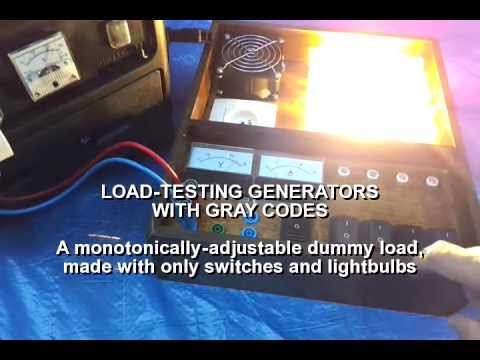
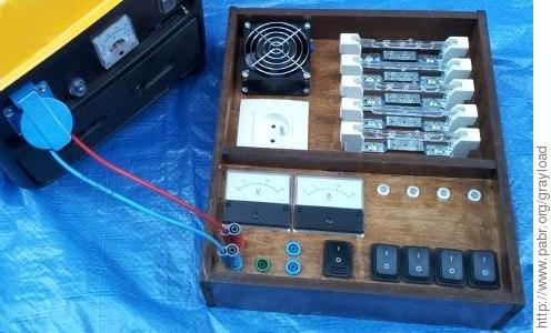
Instead, we will build a dummy load from inexpensive household parts, namely toggle switches and incandescent light bulbs. Dissipated power will be adjustable from 0 to 1500 W in 16 steps of 100 W.


Any number of fixed loads, connected in parallel, will produce an arbitrary equivalent load, as in Figure 1, “ Naive adjustable load ”, but there must be a smarter solution.
Binary codes immediately comes to mind as a way to reduce component count.
Table 1. 4-bit binary code
| Binary | Decimal | Load | Binary | Decimal | Load | |
|---|---|---|---|---|---|---|
| 0000 | 0 | 0 W | 1000 | 8 | 800 W | |
| 0001 | 1 | 100 W | 1001 | 9 | 900 W | |
| 0010 | 2 | 200 W | 1010 | 10 | 1000 W | |
| 0011 | 3 | 300 W | 1011 | 11 | 1100 W | |
| 0100 | 4 | 400 W | 1100 | 12 | 1200 W | |
| 0101 | 5 | 500 W | 1101 | 13 | 1300 W | |
| 0110 | 6 | 600 W | 1110 | 14 | 1400 W | |
| 0111 | 7 | 700 W | 1111 | 15 | 1500 W |
Unfortunately, with binary coding, the load cannot be adjusted monotonically. For example, to increase the load from 700 W to 800 W, we need to change the switch settings from OFF-ON-ON-ON (0111) to ON-OFF-OFF-OFF (1000) - one switch at a time. Whatever order we choose, at some point we will toggle S3, and the load will suddenly increase by 800 W. Such large load variations may cause some generators to stall; other may deliberately shut down rather than supply non-compliant voltage or frequency.
What we need is a circuit such that only one switch needs to be toggled to increase or decrease the load by one step. Fortunately this problem was solved a long time ago, and the canonical solution is Gray codes. In a Gray code, the Hamming distance between consecutive code words is always 1.
Table 2. 4-bit Gray code
| Gray | Binary | Decimal | Load | Gray | Binary | Decimal | Load | |
|---|---|---|---|---|---|---|---|---|
| 0000 | 0000 | 0 | 0 W | 1100 | 1000 | 8 | 800 W | |
| 0001 | 0001 | 1 | 100 W | 1101 | 1001 | 9 | 900 W | |
| 0011 | 0010 | 2 | 200 W | 1111 | 1010 | 10 | 1000 W | |
| 0010 | 0011 | 3 | 300 W | 1110 | 1011 | 11 | 1100 W | |
| 0110 | 0100 | 4 | 400 W | 1010 | 1100 | 12 | 1200 W | |
| 0111 | 0101 | 5 | 500 W | 1011 | 1101 | 13 | 1300 W | |
| 0101 | 0110 | 6 | 600 W | 1001 | 1110 | 14 | 1400 W | |
| 0100 | 0111 | 7 | 700 W | 1000 | 1111 | 15 | 1500 W |
The simple circuit in Figure 3, “ 4-bit Gray-coded adjustable load ” implements this idea. It can be seen as a combined Gray-to-binary-to-analog converter with resistive output. Incidentally, the light bulbs display the value converted to binary.
The circuit is actually four chained copies of the basic cell shown in Figure 4, “ Basic cell; equivalent circuits for S=0 and S=1 ”, minus a few unconnected components. Each cell is a polarity reverser controlled by one bit of the Gray-coded input, plus a fixed load. The polarity reversal is reminiscent of the algorithm for converting Gray codes to binary where code words are read from left to right and subsequent digits are inverted when a "1" is an encountered.
A n-bit-wide converter requires n-2 DPDT switches and two SPDT switches.
After simplifying the layout as in Figure 5, “ Equivalent circuit for Gray code word 0101 (decimal: 6) ”, we see that the device actually has three terminals, although we only use it as a two-terminal variable conductance here.
Since 100+ W incandescent light bulbs and are being banned from stores all over the world, we used 118 mm R7S halogen tubes, which are available from 100 W to 400 W. The 800 W stage is made from two 400 W tubes.
Miscellaneous features were added: Cooling fan, master ON/OFF switch, neon light bulbs, voltage and current meters, socket for extra load.
A suitable shielding window must be added to protect against fires, burns, harmful ultraviolet radiation and exploding tubes.
Because the resistivity of tungsten decreases significantly with temperature, incandescent light bulbs draw more than their rated power for a fraction of a second at cold start. Figure 6, “ Keep all light bulbs on to avoid high inrush currents ” offers a workaround.
Mechanical switches are not perfect. The load will transiently drop for a few milliseconds whenever a double-throw switch is toggled. Also, the construction of the double-pole switches must guarantee proper synchronization between the two poles; otherwise short-circuits may occur.
Capacitors and inductors can be added in order to test generators against adjustable reactive loads.
The toggle switches can be replaced with relays in order to allow Gray code words to be entered electrically rather than mechanically. Similarly, the light bulbs can be replaced with relays in order to output the decoded bits as dry contacts. Such circuits might have been used in the era of early electromechanical computers.
This version combines fixed loads in parallel. The series version is left as an exercise for the reader.
This is a Gray-to-binary converter. Try designing a binary-to-Gray converter, also with mechanical switches only.
Thanks to "rj" for mentioning the high inrush current of incandescent light bulbs.