On February 11th, 2016 the amateur radio community made history by establishing the first direct high-bandwidth amateur video link between the International Space Station and pupils at a British school as part of an educational outreach program. Getting such a system designed, funded, approved by space agencies, built, tested, sent into orbit and installed on the ISS must have been a massive effort spanning more than a decade. Setting up a temporary ground station on school premises for a reliable, highly-publicized direct contact with the ISS is obviously also a huge endeavour involving highly qualified volunteers, sophisticated equipment and careful planning.
On the one hand, such achievements highlight the power of international collaboration and teamwork. On the other hand, they detract from a certain old-school image of amateur radio operators as self-reliant polymaths who can communicate with the whole world with only their knowledge, skills and (preferably self-built) equipment. Hence, after first hearing about HamTV in mid-2015 and seeing the bill of materials for a typical ground station, I began investigating ways to bring this new amateur mode to a wider audience, including students with an interest in science and technology but limited financial resources and no real estate for permanent antennas. My experiments are chronicled in [SOFTDATV] and the present project is their latest outcome.
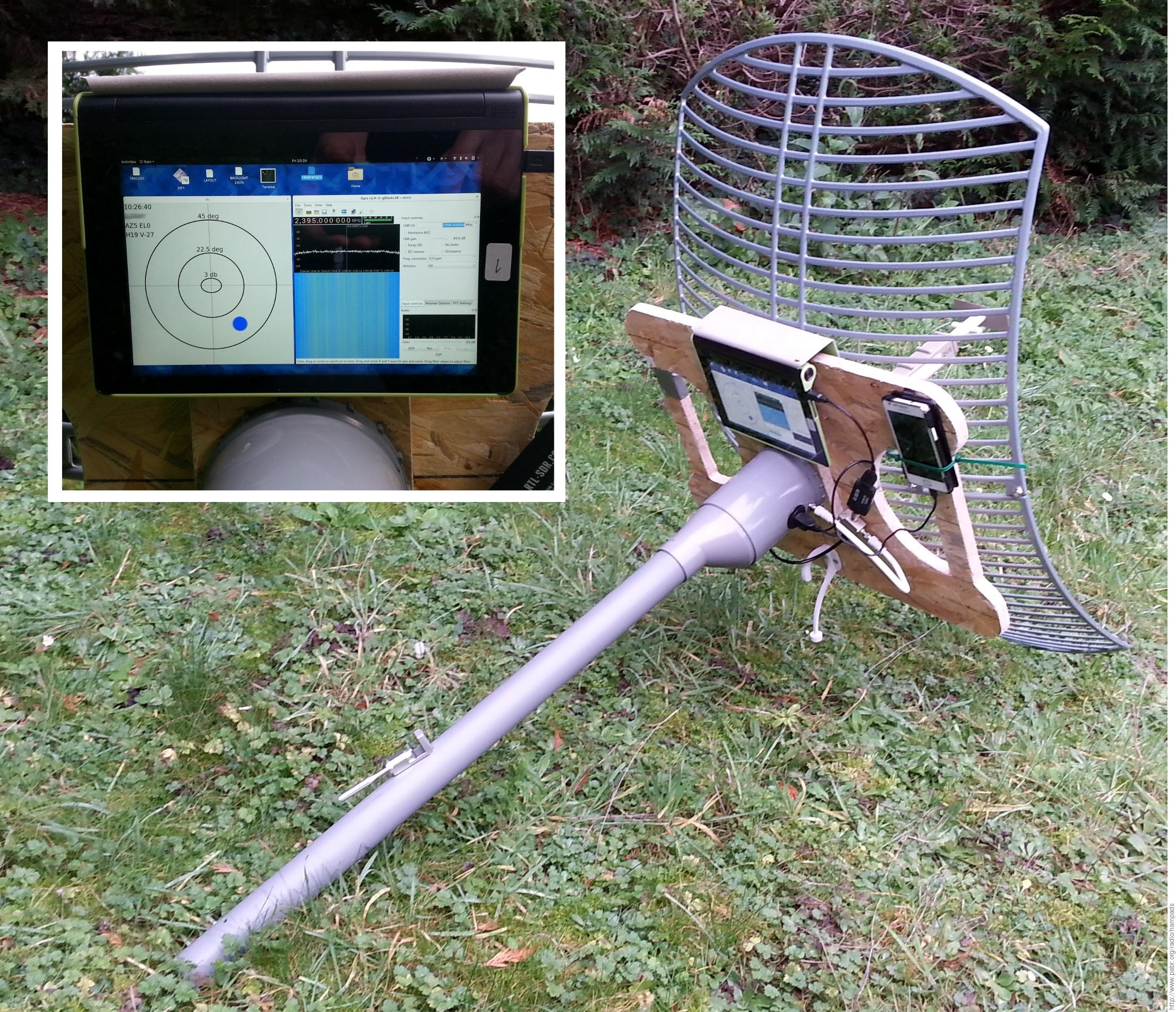
HAMPADS is a shoulder-mounted, manually-operated LEO satellite tracker and HamTV receiver assembled from inexpensive, mass-produced, off-the-shelf components. While it cannot compete with traditional solutions in terms of sensitivity, reliability and power consumption, it might be useful as a low-cost gateway to modern amateur radio and signal processing techniques.
With modifications it could also be used for other applications such as:
- Digital Amateur TV communications between mobile ground stations
- Receiving low-power telemetry from amateur high-altitude balloons and amateur rockets
- Receiving live HD video from remote-controlled aircraft in crowded situations such as drone racing events
- Fingerprinting trespassing UAVs (a highly directional antenna can reliably match RF recordings with a specific aircraft) and triangulating their trajectories (using multiple cooperating ground stations).
The acronym "HAMPADS" is a play on "MANPADS" i.e. shoulder-fired surface-to-air missile systems (which look somewhat similar, unfortunately, simply because form follows function). It serves as a reminder that in this day and age, operating unusual equipment in public places may cause unnecessary disturbance. Should law enforcement officers catch me aiming this contraption at unidentified targets in the sky, my plan is to keep calm and refrain from pointing the scary end toward passers-by.
Of course, the device is completely harmless. It is merely a satellite TV receiver adapted for fast-moving low-earth-orbit transmitters instead of geostationary satellites.
The ISS usually transmits a 10 W EIRP DVB-S signal modulated in QPSK at 2 Msymbols/s with FEC 1/2 on 2395 MHz (see [SOFTDATV] for details and references).
A typical ground station for HamTV comprises a computer-controlled motorized azimuth/elevation rotator capable of slewing 5°/s with 2° accuracy, a 90..120 cm dish with circularly-polarized feed, a custom LNB which brings the signal into the L band, a TechnoTrend DVB-S PCI card in a Windows computer, and the popular Tutioune software by F6DZP. This section reviews the hardware and software functions required, and explains how costs can been reduced.
Table 1. HamTV ground station BoM
| Traditional ground station | Minimum configuration | Tested configuration | Work in progress | |||||
|---|---|---|---|---|---|---|---|---|
| Reflector | 90..120 cm dish | Scrap satellite TV dish (nonmagnetic) | TP-Link TL-ANT2424B (100x60 cm, 24 dBi) | $50 | DIY reflector | |||
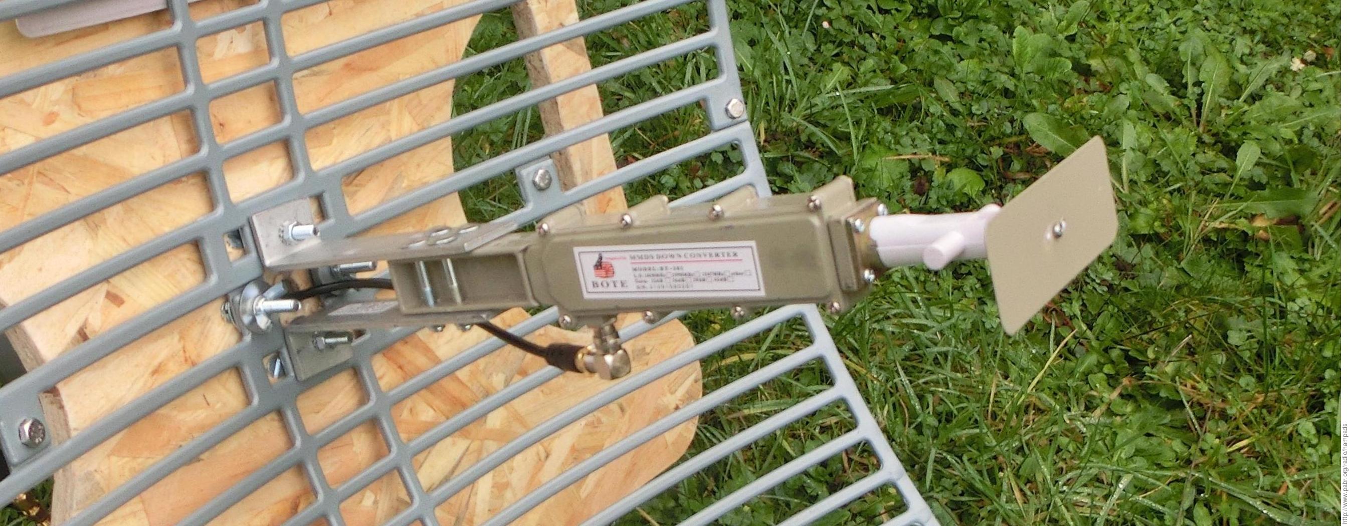
| LNB | S-band to L-band downconverter | $65 | BOTE BT-281B | $12 | BOTE BT-281B | $12 | BOTE BT-281B | $12 |
| Feed | Helical feed | Integrated dipole of BT-281B | Integrated dipole of BT-281B | DIY helical feed | ||||
| RF cable 1 | 50 cm F-type cable | $6 | Right-angle F-type adapter, 50 cm F-type cable | $10 | Right-angle F-type adapter, 50 cm F-type cable | $10 | ||
| Bias tee | Built into DVB-S card | BT-288K | $5 | Satellite TV Line Power Inserter | $15 | Satellite TV Line Power Inserter | $15 | |
| LNB power supply | Built into DVB-S card | Mains adapter supplied with BT-288K | 14.4 V NiMH battery pack | 14.4 V NiMH battery pack | ||||
| RF cable 2 | F-to-MCX cable | $6 | F-to-SMA adapter | $5 | F-to-SMA adapter | $5 | ||
| Receiver | TechnoTrend PCI card | $100 ? | RTL-SDR R820T2, MCX, plastic | $10-$15 | RTL-SDR R820T2, TCXO, SMA | $25 | RTL-SDR R820T2, TCXO, SMA, aluminium | $25 |
| Receiver power supply | From PC | USB from tablet/laptop | Powered USB hub or splitter cable | USB Accessory Charger Adapter | ? | |||
| Tracking and pointing | Az/El antenna rotator | $800 ? | Smartphone with satellite tracking app | Linux tablet with custom software | Android phone with HAMPADS app | |||
| Signal acquisition | Windows PC | Linux laptop with gqrx | Linux tablet with gqrx, USB OTG cable | Android phone with HAMPADS app | ||||
| Phone/tablet power supply | Built-in battery only | Built-in battery only | USB Accessory Charger Adapter | |||||
Satellite tracking is a well-known topic in amateur radio and astronomy circles. Algorithms, free software and up-to-date orbital parameters are easily found online.
The Az/El antenna rotator is the most expensive item in a traditional HamTV ground station. A DIY rotator may turn out to be less expensive than commercial offerings, but that is beyond the scope of this project. An obvious alternative is to aim the antenna manually. After all, many amateurs enjoy working satellites on 2 m and 70 cm with hand-held Yagi antennas. Unfortunately the link budget for HamTV requires antennas with much higher gain. Pointing must be accurate to a few degrees.
Note that a fixed antenna, properly positioned in advance, can provide good reception for 10..20 seconds during overhead passes. See [IZ8YRR] and [SOFTDATV]. This is enough to get started and addicted to the thrill of seeing the signal rise from the noise floor at the exact time predicted by orbit simulations.
My solution relies on mobile apps which display an "augmented reality" view of the sky. Using the GPS receiver, tilt sensor and magnetic compass found in modern smartphones, these applications allow any non-technical user to locate satellites (and a variety of celestial objects) by holding their phone in the air and following visual cues. If an antenna is attached to the phone and aligned with its frame of reference, it will also point toward the selected satellite. Note that this is not a new idea; for example, see this 2012 video by HB9EYY featuring an app called "Satellite AR".
Eventually I wrote my own satellite pointing program for Linux. Orbit prediction relies on the Python PyEphem package, which is derived from the well-known XEphem software by WB0OEW. Unfortunately the pointing functionality runs only on a specific tablet (Lenovo Yoga Tab 2 modified to run Linux) because it uses dedicated drivers for the inertial and magnetic sensors.


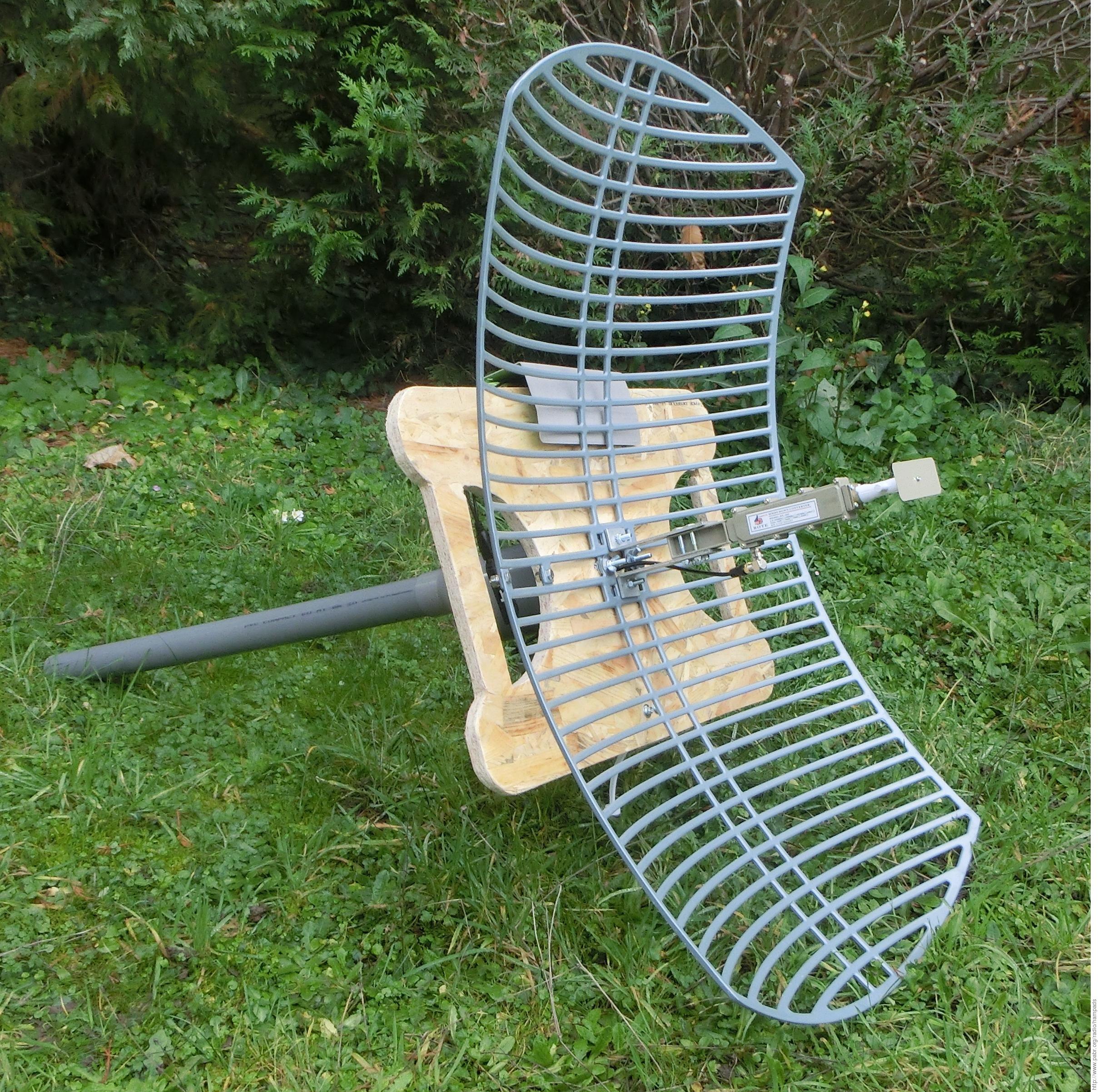
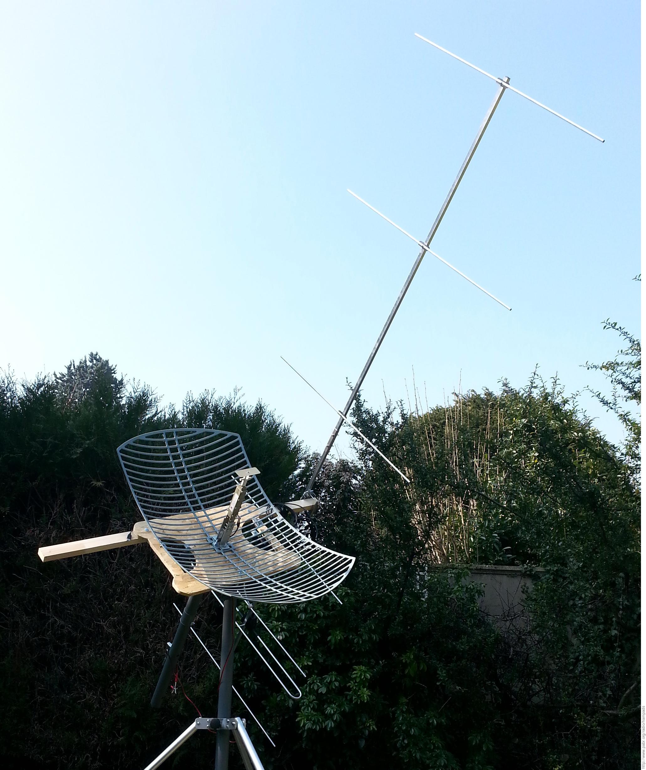
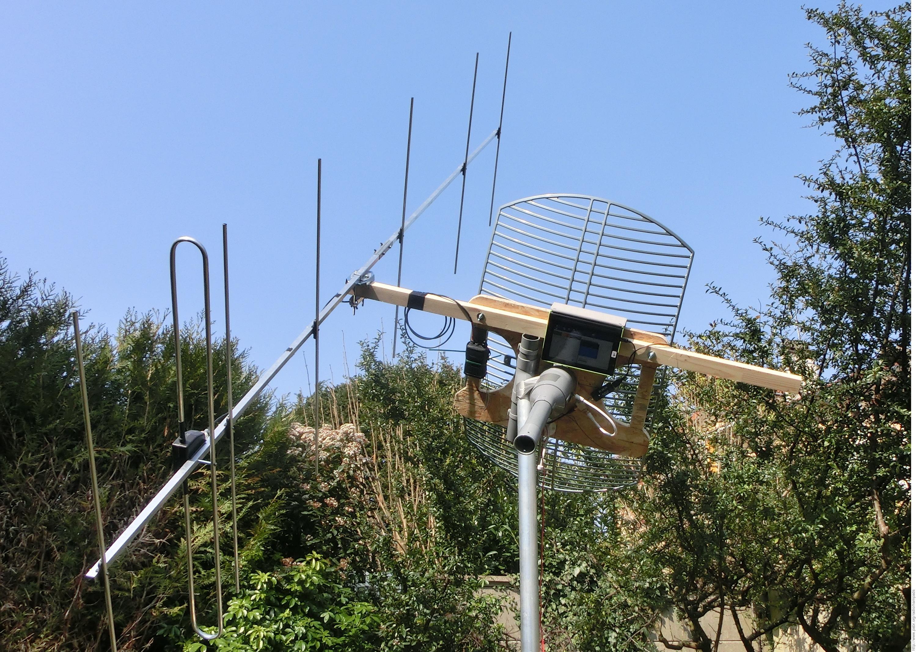
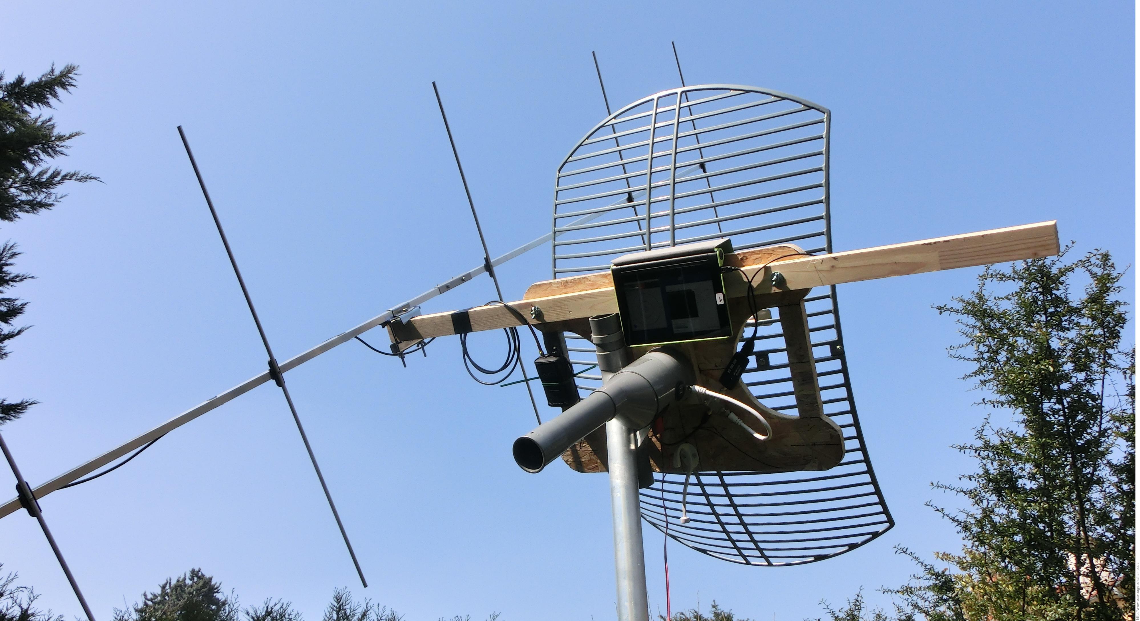
Instead of a dedicated satellite dish, I used a 24 dBi linearly-polarized prime focus grid parabolic WiFi antenna which is relatively inexpensive and widely available worldwide.
With the sideways orientation shown in the pictures, the beam pattern is spread horizontally. This matches the error pattern of the pointing system: Azimuth, which is determined magnetically, is typically less accurate than elevation, which is measured by inertial sensors.
After a few iterations of the project, this antenna has become the most expensive component, and I am not even using its 2.4 GHz dipole feed. So it is now worth exploring alternatives. Any sufficiently large scrap satellite TV dish should work, but those are usually offset designs. This makes mechanical assembly and aiming more complicated. Note that non-ferrous materials are preferred because the pointing system relies on magnetic sensors mounted near the antenna.


While investigating amateur radio activities in the S band, I found articles by M0DTS, G0ORY and JN1GKZ about inexpensive MMDS downconverters.
The BOTE BT-281B turned out to be suitable for HamTV reception, except that its output is near 400 MHz, i.e. well below the rated tuning range of commercial DVB-S receivers. But this can be received by inexpensive SDR front-ends (see below).
Another problem is that the BT-281B comes with a built-in linear dipole. Experienced hobbyists may want to replace it with a helical feed to improve reception by 3 dB. In that case, a solid dish should be used instead of a grid-parabolic reflector.


A digital satellite TV receiver comprises an analog front-end, a DVB-S demodulator and a MPEG decoder. It turned out that the incredibly inexpensive "RTL-SDR" USB dongles can capture downconverted HamTV signals. Baseband I/Q samples can then be fed into a free software-defined demodulator (see [SOFTDATV] and [LEANDVB]). The resulting MPEG Transport Stream can be decoded and displayed with a variety of applications.
Alternatively, I/Q samples can be recorded to disk and demodulated later. One of the benefits of SDR is that the fun does not end when the ISS goes below the horizon. Video quality can be improved afterward by tweaking demodulator parameters, filtering spurious signals manually, etc. Besides, as with many digital transmissions, data fragments from multiple receive chains (or even from multiple ground stations) can be combined to reconstruct an error-free video stream.
RTL-SDR dongles can reliably sample I/Q signals up to 2.4 MHz (higher rates cause data loss). Besides, anti-aliasing filters cause attenuation near band edges; this reduces the usable bandwidth. DVB-S signals from the ISS occupy 2.7 MHz of RF spectrum. Fortunately the actual modulation uses only 2 MHz and the rest is roll-off. It is quite remarkable that digital signal processing techniques can successfully demodulate a QPSK signal with just a bit more than one I/Q sample per symbol.
RTL-SDR dongles typically ship with MCX connectors. Some variants have a F-type connector instead. Models advertised for SDR often have a SMA connector.
In this application the signal is amplified by the MMDS LNB, so the choice of connector or cable type is unlikely to affect performance.

Some RTL-SDR dongles can be easily modified to inject 5 V into the RF cable. This is suitable for active DVB-T and GPS antennas. Unfortunately satellite and MMDS LNBs expect 13 V or 18 V.
The BT-281B MMDS downconverter is sometimes bundled with a compatible bias tee, reference BT-288K. It has an attached 18 V 300 mA mains adapter. The LNB contains a 8 V, 500 mA linear regulator (78M08), so any voltage between 12 V and 18 V would probably work.
For wire-free operation I added twelve NiMH AA batteries (14.4 V 2500 mAh). The battery pack is mounted at the rear of the boom to help balance the weight of the device.
RTL-SDR dongles are usually powered by their USB host. My dongle typically draws 70 mA when idle and 270 mA while active. To reduce the load on the USB host, the dongle can be connected via a powered USB hub, and the hub can be powered from the same battery pack as the LNB.
I also tested a USB OTG "splitter" cable which has a type-A plug in addition to the expected micro-B plug and type-A receptacle. The type-A end plugs into a 12..24 V automotive USB adapter. I do not recommend this solution because the design of this specific cable does not appear to be electrically sound.
Digital signal processing puts a heavy load on the CPU, and the display will typically be set to maximum brightness for outdoor use. Therefore it would be useful to plug the device into an external power supply. Unfortunately most smartphones and tablets have only one USB port, and therefore they cannot charge while a RTL-SDR dongle is connected.
In theory the USB Accessory Charger Adapter standard allows a device to simultaneously charge and act as a USB OTG Host, but it is unclear which smartphones and tablets support it.
Wireless (i.e. inductive) charging pads near magnetic sensors and radio equipment do not sound appealing, but this might work in practive.
The system was first tested during British astronaut Tim Peake's "Principia" mission in early 2016. ARISS video contacts between Tim Peake and several schools were scheduled to occur while the ISS was above the UK. I did record the very first ARISS HamTV contact on February 11th, 2016 at 47° maximum elevation from France. SNR was not good enough for real-time demodulation with leandvb, but I was able to recover 11 MB of MPEG Transport Stream afterward with a more sophisticated software demodulator (gr-dvb).
The last "Principia" contact on May 9th, 2016 occurred with good weather and 67° elevation. This made it possible to demodulate and decode 16 MB of MPEG video (i.e. about 70 s) in real-time.
Testing will resume during French astronaut Thomas Pesquet's "Proxima" mission.
Amateur radio is about two-way communication, not just receiving TV broadcasts (be they from a space station). Right now the ISS cannot receive amateur video from the ground. But why not add a VHF voice uplink by attaching a mobile transceiver and directional antenna to the dish ?
Note: The tripod mount is not part of the system. The dish must still be held at shoulder height and swept across the sky. A three meter long 144 MHz Yagi antenna balanced at that height will swivel freely in a vertical plane. Total weight is about 10 kg.
Can we make HamTV reception even simpler and less expensive ?
First, we could package all the software (tracking, pointing, DVB-S demodulation and MPEG decoding) into a single easy-to-use smartphone app.
Then, we could build inexpensive reflectors out of aluminium foil.
Finally, note that modern smartphones contain a variety of radios (FM, GSM, 3G, LTE, Bluetooth, Wi-Fi, GPS). Manufacturers are reluctant to publish datasheets for their chipsets but we can reasonably assume that in theory, some of them could be reprogrammed to serve as SDR receivers. Then we could receive HamTV by positioning a smartphone at the focus of a parabolic reflector.
[IZ8YRR] HamTV reception with a low gain antenna . 2014. http://www.amsat.it/HAMTV%20reception%20with%20a%20low%20gain%20antenna%20-%20IZ8YRR%2020150714.pdf.
[SOFTDATV] SDR reception of Digital Amateur TV from the ISS . http://www.pabr.org/radio/softdatv/softdatv.en.html .
[LEANDVB] leandvb: A lightweight software DVB-S demodulator . http://www.pabr.org/radio/leandvb/leandvb.en.html .