


Since May 2015 amateur radio operators can receive digital video directly from the International Space Station (ISS), at considerably higher quality than with earlier modes such as slow-scan TV. This was not publicized until February 2016, when this system was used for the first direct video contact between an astronaut and a school as part as an educational outreach program. Most of the time, the ISS only transmits a blank test pattern. But astronauts have a long tradition, dating back to the Mir era, of communicating with amateur radio operators in their free time. So anyone with the right skills and equipment can try to receive unscheduled transmissions or even (with a license to transmit) attempt to have their own video chat with the ISS.
Digital video on the amateur bands is known as "Digital Amateur TV", "Digital ATV" or "DATV". Amateurs typically use the same standards as mainstream digital TV broadcasts: DVB-S (satellite) and DVB-T (terrestrial). In the context of DATV on the ISS, "Ham Video" refers to the on-board transmitter, and "Ham TV" designates the video downlink combined with a voice uplink for two-way contacts.
Forum DATV (vivadatv.org) - A prominent DATV community forum.
BATC forum (batc.org.uk) - A British ATV community forum with DATV sections
Receiving DVB transmissions from the ISS presents unique challenges, compared with other DATV activities:
Link budget . The ISS transmits only about 10 W EIRP. The closest distance is about 400 km (for a brief moment during favourable passes). The recommended receive antenna is a 1.2 m dish. Based on DVB-S specifications ([DVBS]) and FEC settings, Eb/N0 ≥ 4.5 dB is required for quasi-error-free reception.
Tracking . Unlike terrestrial DATV stations and geostationary satellites, the ISS is a moving transmitter. For optimal reception, a computer-controlled motorized azimuth/elevation rotator accurate to ±2° and capable of slewing 5°/s is recommended. (But results can also be obtained with small, fixed antennas - see below.)
Polarization . Circularly polarized antennas are harder to procure or build than linearly polarized ones.
Frequency . Most DATV activity occurs in the 70 cm and 23 cm bands which happen to be within the tuning range of mainstream DVB-T and DVB-S receivers. For technical reasons the ISS transmits in the 13 cm band (2369, 2395, 2422 or 2437 MHz). Therefore frequency converters or dedicated receivers are required.
Background noise . Depending on transmitter settings, the signal falls either within or very close to the 2.4 GHz ISM band which is also used by WiFi, Bluetooth and microwave ovens.
Bandwidth . The ISS typically transmits at 2 Msymbols/s, which translates to 2 MHz of RF bandwidth (2.7 MHz with roll-off). This is within the capabilities of some amateur SDR equipment. Ultra-low-cost RTL-SDR USB dongles can achieve meaningful results, but this requires extra care.
Ground network . Since a station can only receive video for a few minutes during each pass of the ISS, a network of ground stations is required in order to achieve longer contacts. At the time of writing there is a repeater at http://www.batc.tv/iss/.
Background information and resources:
A DATV transmitter on Columbus (ariss-eu.org) - Project history and credits (PDF)
HAM Video (ariss-eu.org) - Technical details and pictures of the antennas
HAM-TV (kayser.it) - Website of the company that supplied the transmitter
HamTV on the ISS (ariss.org) - News feed
HamTV Experiment on-board ISS (amsat.it) - Design considerations and link budget (PDF)
Simple Station for the Ham Video Launch Campaign (ariss.org) - Recommended equipment, DIY helix antennas (PDF)
ARISS reception reports during the 2014 test campaign (spaceflightsoftware.com) - Compares results achieved with various types of antennas
Current Status of ISS Stations (ariss.org) - The transmitter is shut down whenever the crew needs the 28 V DC power supply for other purposes.
One goal of the present project is to significantly reduce costs and other barriers to entry. [IZ8YRR] already showed that interesting experiments can be performed with a small 12 dB fixed antenna.
Another goal is to explore the benefits of software-defined radio (SDR). Many DATV experiments are already conducted with software-defined DVB modulators, but the receive side usually consists of black-box demodulators embedded in PCI cards, USB dongles or standalone set-top-boxes ([N6GHZ]). Open-source software-defined receivers are a good introduction to modern signal processing techniques, offer more flexibility in demodulation strategies, and achieve independence from the product life cycle of specific off-the-shelf components.


My first successful experiment used the following receive chain.
Hardware:
TP-Link TL-ANT2424B 2.4 GHz 24 dB WiFi grid parabolic antenna. The linear polarization wastes 3 dB, but this is a relatively inexpensive and widely available product, unlike helical antennas.
BOTE BT-480 low-noise amplifier and downconverter (3650±1.5 MHz LO, 50 dB gain, 0.4 dB noise). This is the only specialized component in this project.
Generic 5 - 2400 MHz satellite TV splitter.
Xtrend ET 4000 satellite set-top-box running embedded Linux. I intended to confirm the presence of a valid signal with this off-the-shelf receiver, prior to working on the software-defined receiver, but it did not detect anything. Eventually it only served as a 13 V power supply for the downconverter.
Ettus Research USRP with DBSRX front-end (800 - 2300 MHz, 12-bit I/Q sampling at 8 MS/s). This is the most expensive component in this project. Future work will focus on finding alternative SDR hardware.
Generic laptop (Intel Celeron 2955U 1.4 GHz) running Linux.
Software:
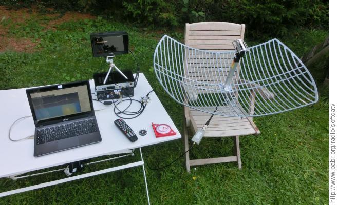
Figure 1. Setup with fixed 24 dB antenna
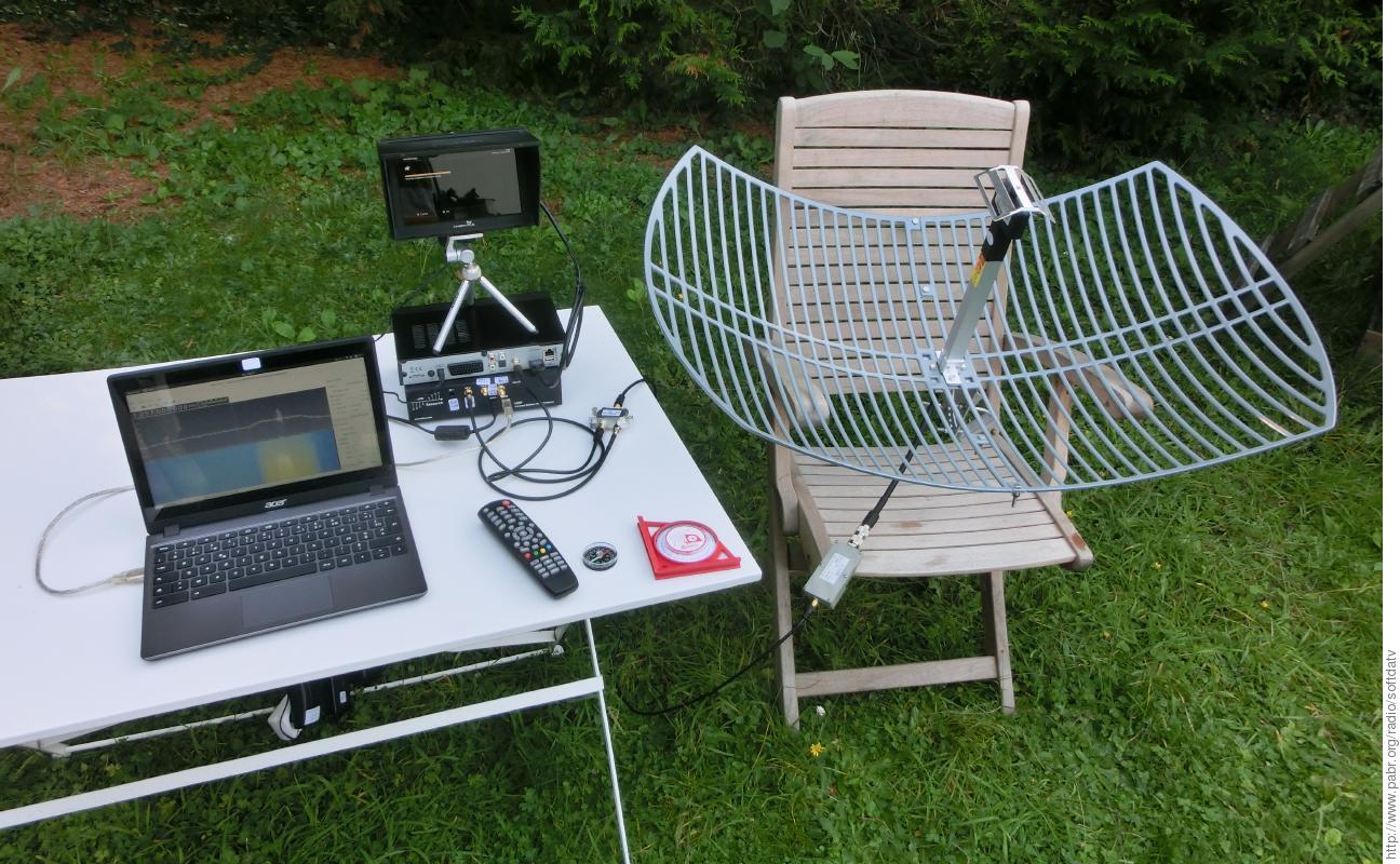
Laptop running GQRX, set-top-box and monitor, USRP, splitter, compass and inclinometer, downconverter, antenna.
The waterfall display is from a recording; the ISS was not transmitting on the day when the picture was taken.


How to receive:
Look up local coordinates with a GPS receiver or on Google Maps.
Use gpredict to select passes of the ISS reaching above 60° elevation. Confirm with an online satellite pass prediction service such as AMSAT. Account for time zones and daylight savings.
Check whether the transmitter will be active. ARISS seems to have up-to-date information here.
Manually point the antenna toward the highest point of the predicted trajectory above the horizon.
Initiate scanning on the set-top-box receiver, at least to enable the 13 V supply to the downconverter.
Run gqrx. Tune to 1255 MHz (or 3650 MHz minus the transmit frequency, if not 2395 MHz).
Adjust gains:
GC1~40dB, GC2=0, ADC-pga=0. Hopefully system noise is minimized by saturatingGC1first.When the signal appears in the waterfall spectrum view, start capturing raw I/Q data. The signal may be off-center due to the poor accuracy of the LO of the downconverter. Try to estimate the offset; this will help with software demodulation.
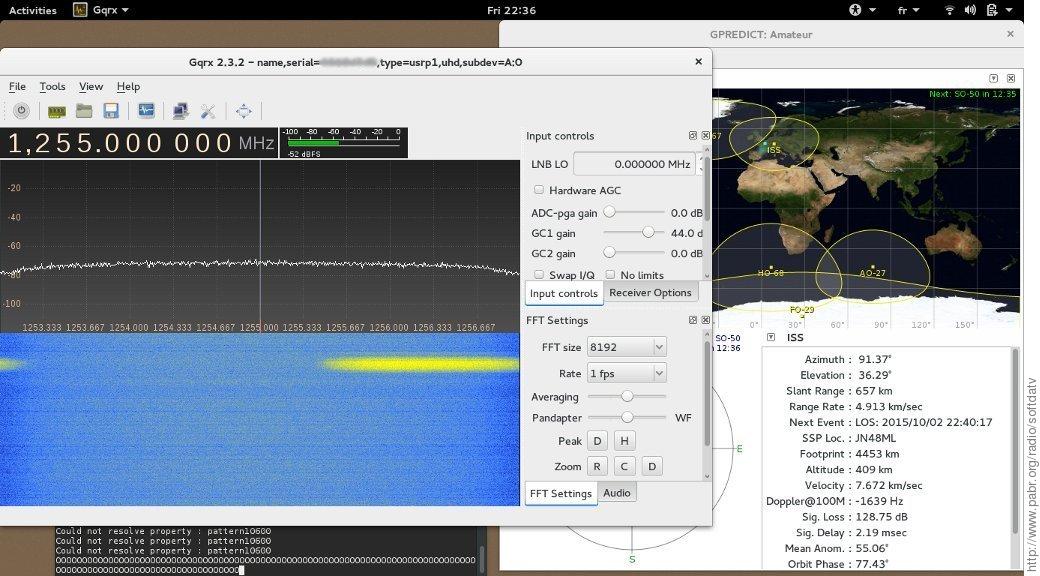
Figure 2. First successful reception
... except for unexpected frequency offset, presumably from downconverter.
How to demodulate and decode:
Use this script (largely inspired from [GRDVB]):
#!/usr/bin/env python

# export PYTHONPATH=gr-dvb-pabr/swig:gr-dvb-pabr/swig/.libs:gr-dvb-pabr/python

file = "gqrx_YYYYMMDD_hhmmss_FFFFFFFFFF_RRRRRRR_fc.raw"
sample_rate = 8e6
symbol_rate = 2000e3
freq_shift = 0e3

from gnuradio import gr
import dvb_swig
import dvb_s_modulator, dvb_interleaver_bb

tb = gr.top_block("DVBS_Receiver")

src = gr.file_source(gr.sizeof_gr_complex, file, False)
mixer = gr.multiply_cc()
tb.connect(src, (mixer,0))
freq_offset = gr.sig_source_c(sample_rate, gr.GR_SIN_WAVE, freq_shift, 1, 0)
tb.connect(freq_offset, (mixer,1))

demod = dvb_s_modulator.s_demodulator_cc(sample_rate, symbol_rate)
#demod = dvb_s_modulator.s_demodulator2_cc(sample_rate, symbol_rate)
puncturing = [1,1]  # For rate 1/2
decode = dvb_swig.depuncture_viterbi_cb(puncturing)
deinterleaver = dvb_interleaver_bb.deinterleaver_bb()
pad = dvb_swig.pad_dvb_packet_rs_encoded_bp()
rs_decoder = dvb_swig.rs_decoder_pp()
derandomizer = dvb_swig.derandomizer_pp()
depad = dvb_swig.depad_mpeg_ts_packet_pb()
dst = gr.file_sink(gr.sizeof_char, "out.ts")

tb.connect(mixer, demod, decode, deinterleaver, pad,
           rs_decoder, derandomizer, depad, dst)

tb.run()
Decode the resulting MPEG Transport Stream:
$ mplayer out.ts
or
$ ffplay out.ts
During this capture (in early October 2015) the ISS was transmitting with the following parameters. Note the surprisingly high audio bitrate.
Stream #0.0[0x100]: Video: mpeg2video, yuv420p, 720x480 [PAR 8:9 DAR 4:3], 903 kb/s, 35.45 fps, 59.94 tbr, 90k tbn, 59.94 tbc
Stream #0.1[0x101]: Audio: mp2, 44100 Hz, 2 channels, s16, 256 kb/s


I was able to demodulate and decode signals captured by a low-cost RTL-SDR USB dongle sampling 8 bits (I/Q) at 2.4 MS/s with the same hardware as above. Additional precautions were required:
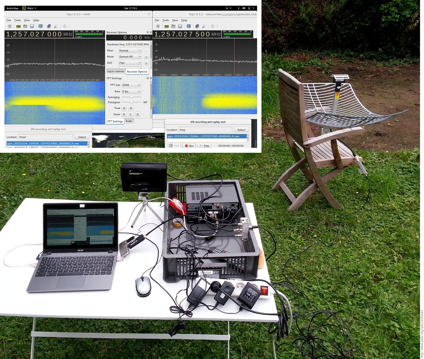
Tune the RTL-SDR dongle as close as possible to the center frequency of the signal, to prevent attenuation near band edges and/or aliasing . I knew from previous attempts that my downconverter was at least 1 MHz off, so I tuned to 1256 MHz instead of 1255 MHz. I started a second instance of GQRX with the USRP sampling at 4 MS/s so that I could visually estimate the real frequency of the signal as soon as it rose from the noise floor. I quickly adjusted the tuning of the RTL-SDR dongle in the first GQRX instance. This can be seen in the waterfall display in Figure 4, “ Setup with three-way splitter and RTL-SDR dongle. ”. Then I still had time to capture a few seconds of data to disk before the ISS left the field of view of the antenna. This could be done automatically and without a USRP, by having the dongle scan a few MHz around the nominal frequency until the signal is found.
Bypass the frequency-locked loop of
gr-dvb(digital.fll_band_edge_cc()inpython/dvb_s_modulator.py) . It works reasonably well with a 2 MHz signal sampled at 4 MS/s, but not so much at 2.4 MS/s.Manually correct any frequency error to within 10 kHz . Simply adjust
freq_shiftuntil overall packet loss is minimized.

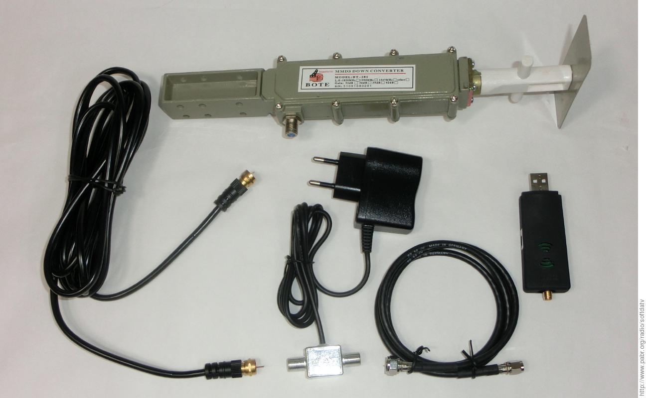
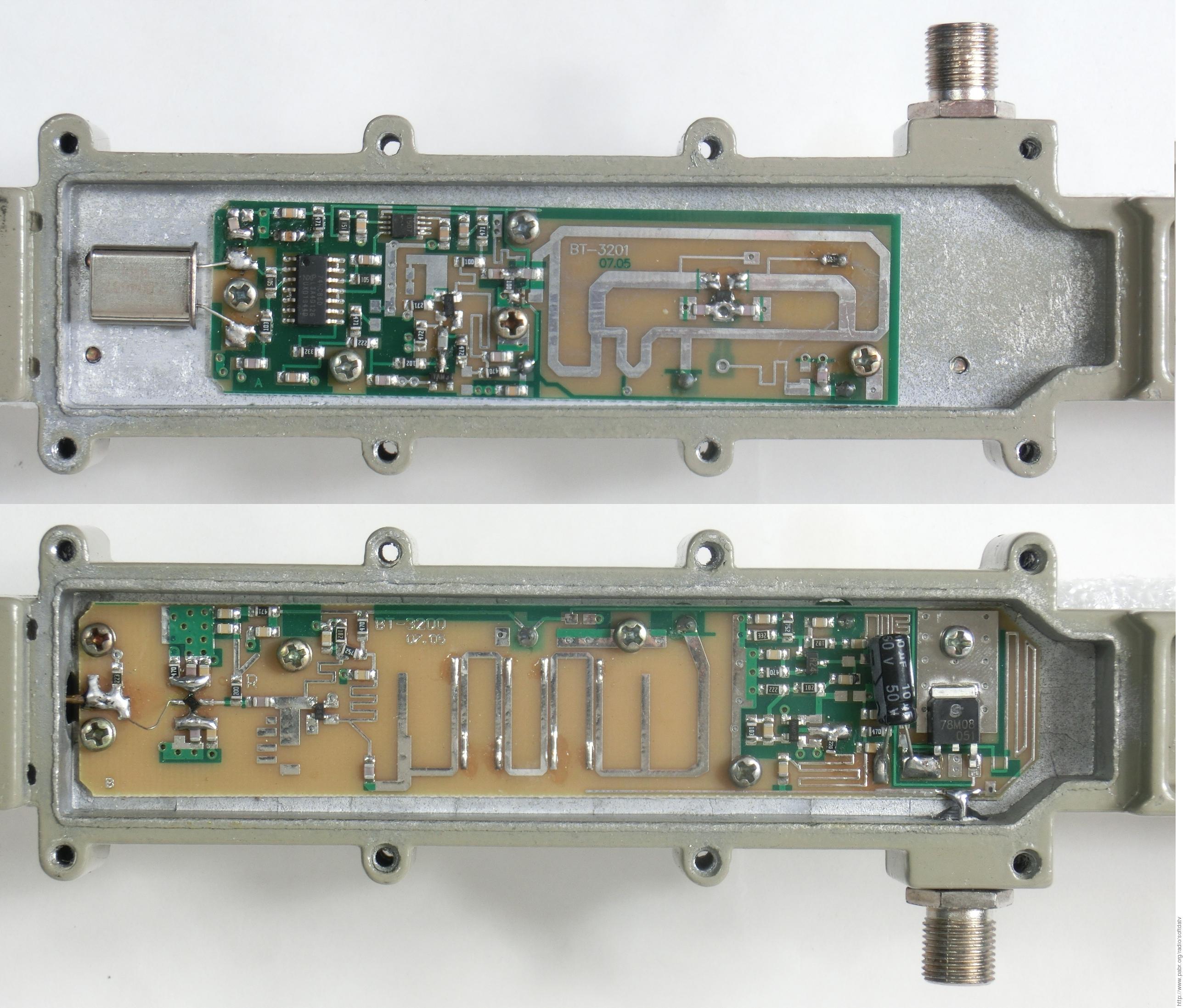
Inexpensive MMDS downconverters are popular for amateur radio applications in the 13 cm band. See for example:
It should be possible to receive DATV from the ISS with the following setup. (The variant I actually tested had a TCXO dongle and SMA connections.)
- 24 dBi reflector (possibly a scrap satellite TV dish, or DIY)
BOTE BT-281B MMDS LNB (2200 - 2400 MHz, 1998±0.030 MHz LO, 39 dB gain, 1.2 dB noise): $12
BOTE BT-288K bias tee (18 V, 300 mA, European plug): $5
F to MCX cable: $6
Generic R820T2 dongle (MCX, non-TCXO) : $10 - $15
Linux PC (or possibly a smartphone with USB OTG)
Software-defined demodulator.
Note that the LNB output is near 400 MHz. This is below the tuning range of common DVB-S receivers.
The BT-281B downconverter has better rated frequency accuracy than the BT-480: ±30 kHz instead of ±1.5 MHz. The additional error from a non-TCXO RTL-SDR dongle is typically less than 100 ppm, i.e. ±40 kHz at 400 MHz. So there is no need for a spectrum scope to locate the signal as in Section 4, “ ISS DATV reception with a RTL-SDR USB dongle ”. Besides, the total frequency error is one order of magnitude smaller than the 2 MHz symbol rate; most demodulators should tolerate that. However, since DVB-S signals from the ISS occupy almost the whole bandwidth of a RTL-SDR dongle running at 2.4 Msamples/s, it is a good idea to keep the signal centered in order to avoid attenuation near band edges. Therefore a TCXO variant is worth the additional cost.
Note that Doppler shift is negligible for such wide-band signals.
Figure 5. Setup with MMDS LNB and RTL-SDR dongle
(Pictured with a SMA dongle; MCX models are less expensive.)
The BT-283 variant has an integrated Yagi antenna with unspecified gain instead of a dipole, but its rated input range is 2500 - 2700 MHz. I tested it during an overhead pass of the ISS and could barely see the signal. It is unclear whether the LNA has too much attenuation at 2395 MHz or whether the antenna itself does not have enough gain.
Textbook DVB-S demodulation techniques, as implemented in gr-dvb, are CPU-intensive. I wrote a simpler demodulator which trades sensitivity for real-time performance on low-power hardware: see [LEANDVB].
The high latency and/or power requirements of software-defined demodulators make them unsuitable for some applications. Therefore, I also investigated dedicated DVB-S receivers. The evaluation criteria are:
Support for low symbol rates (down to 1.3 Msymbols/s)
Ability to tolerate large frequency offsets from low-cost downconverters
Behaviour at low SNR
Ability to parse the Transport Stream of the ISS (which is not formatted exactly like mainstream DVB-S broadcasts).
Since the ISS is in direct line of sight for only a few minutes per day, it would have been impractical to experiment with the live signal. Instead, I connected the devices under test to a USRP with RFX2400 daughter board, and I played back a 4 MS/s recording on 2395 MHz.
I also connected the RTL-SDR dongle in parallel for troubleshooting. This confirmed that the L.O. of the 3650 MHz downconverter is not very reliable.
These chips are found in the TechnoTrend S2 1600, a PCI DVB-S receiver that is popular in the DATV community (at least on Windows).
With custom programming, this card can reportedly tune up to 2600 MHz, i.e. it should be able to receive DATV from the ISS without a downconverter, assuming an antenna with sufficient gain.
These chips are found in the TechnoTrend S2 3200, another popular PCI receiver for DATV. According to the manufacturer they are being EOL'ed.

These chips are found in low-cost USB receivers. I tested the DVBSky S960DVBSky S960DVBSky S960.
Create iss.conf with a virtual transponder at 11.255 GHz:
[ISS]
    SERVICE_ID = 2395
    VIDEO_PID = 256
    AUDIO_PID = 257
    DELIVERY_SYSTEM = DVBS
    FREQUENCY = 11255000
    SYMBOL_RATE = 2000000
    INNER_FEC = 1/2
    POLARIZATION = VERTICAL
    MODULATION = QPSK
    INVERSION = AUTO
Tell dvbv5-scan we have a "standard" LNB, which implies a L.O. of 10.000 GHz. The dongle will actually tune to 1255 MHz, which is 2395 MHz downconverted by the BT-480.
# dvbv5-scan  -l STANDARD  -v  -T 100  iss.conf
ERROR    command BANDWIDTH_HZ (5) not found during retrieve
ERROR    command MODULATION (4) not found during store
...
       (0x00) Signal= 100.00% C/N= 0.00% postBER= 0
       (0x00) Signal= 100.00% C/N= 0.00% postBER= 0
       (0x00) Signal= 100.00% C/N= 0.13% postBER= 0
       (0x00) Signal= 100.00% C/N= 0.11% postBER= 0
Lock   (0x1f) Signal= 100.00% C/N= 0.12% postBER= 0
A signal is detected but the channel scan fails because the ISS stream does not contain Program Map Tables, unlike commercial satellite TV broadcasts.
Since we specified the PIDs manually we can retrieve the MPEG Transport Stream anyway:
# dvbv5-zap  -l STANDARD  -c iss.conf  ISS  -r
using demux '/dev/dvb/adapter0/demux0'
reading channels from file 'iss.chan'
ERROR    command MODULATION (4) not found during store
tuning to 11255000 Hz
video pid 256
  dvb_set_pesfilter 256
audio pid 257
  dvb_set_pesfilter 257
...
       (0x00) Signal= 100.00% C/N= 0.22% postBER= 0
       (0x00) Signal= 100.00% C/N= 0.13% postBER= 0
       (0x00) Signal= 100.00% C/N= 0.15% postBER= 0
DVR interface '/dev/dvb/adapter0/dvr0' can now be opened
# hexdump -C /dev/dvb/adapter0/dvr0
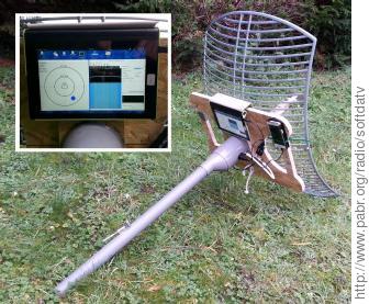
As an intermediate step between fixed antennas and fully-automated Az/El rotators, it is possible to point a dish manually by equipping it with a smartphone running an "augmented reality sky" app. These apps use the GPS, magnetic and inertial sensors found in modern smartphones, together with orbital parameters downloaded from online sources, to visually guide the user toward any satellite. See [HAMPADS].
Amateur radio antenna rotators are expensive. They are often dimensioned for 100+ kg payloads and all-weather operation.
Automatic satellite TV antennas intended for recreational vehicles (RVs) could be an interesting starting point for lightweight dish rotators. Similar antennas are also available for recreational boats, presumably with faster actuators.
I am building a motorized swivel-and-fork mount for the 24 dB antenna and also investigating other options.


Figure 8. LEGO tracker for LEO satellites
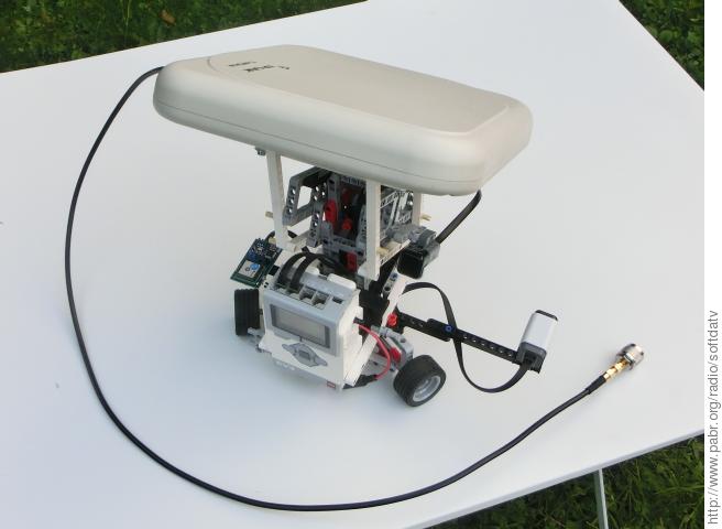
LEGO rotator with GPS, compass and tilt sensor, pointing a 700 gram 14 dB antenna.
Recent digital satellite television standards, such as DVB-S2 and H.264, can transmit HD video. By contrast, ISS DATV uses DVB-S and MPEG-2 (which were designed around 1995) and a low bitrate. On the one hand, video quality might turn out to be disappointing (lower than DVD quality). On the other hand, all relevant patents have expired or will expire shortly in most countries.
Thanks to Edmund Tse for publishing the source code and technical report for his DVB project. Anyone who has implemented ETSI standards from scratch can appreciate the effort that went into it.
Tonino Giagnacovo IZ8YRR and Fabrice Bellard helped validate the receive chain.
[DVBS] Digital Video Broadcasting (DVB); Framing structure, channel coding and modulation for 11/12 GHz satellite services . 1997. https://portal.etsi.org/webapp/WorkProgram/Report_WorkItem.asp?WKI_ID=5316.
[N6GHZ] Low Cost DVB-S Receivers Suitable For HAMTV Reception . 2013. http://ww2.amsat.org/xtra/N6GHZ_HAMTV_Article.pdf.
[IZ8YRR] HamTV reception with a low gain antenna . 2014. http://www.amsat.it/HAMTV%20reception%20with%20a%20low%20gain%20antenna%20-%20IZ8YRR%2020150714.pdf.
[GRDVB] Software Radio for Digital Satellite Television . 2010. http://www.edmundtse.com/wp-content/uploads/2009/04/treatise.pdf.
[LEANDVB] leandvb: A lightweight software DVB-S demodulator . http://www.pabr.org/radio/leandvb/leandvb.en.html .
[HAMPADS] HAMPADS: HAM-Portable Affordable Dish for Satellites . http://www.pabr.org/radio/hampads/hampads.en.html .