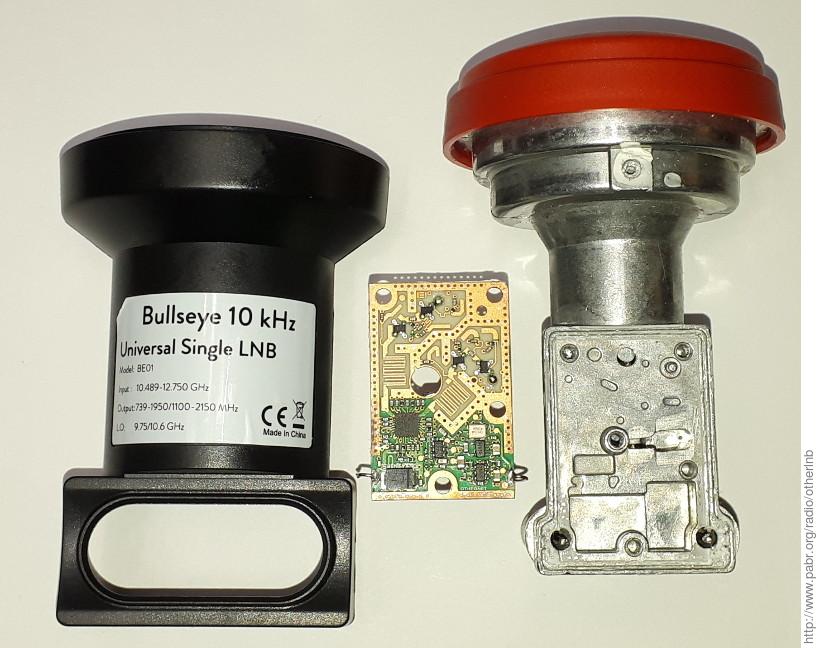
BE01 mounted on 120 cm dish, powered by bias tee
IF output connected to a PlutoSDR via low-pass filter and attenuator
PlutoSDR TCXO disabled by grounding pin 1
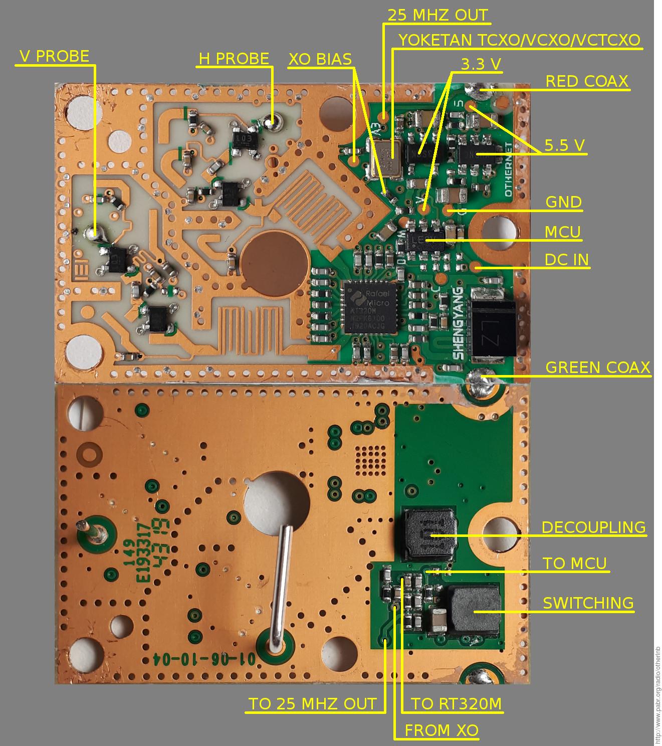
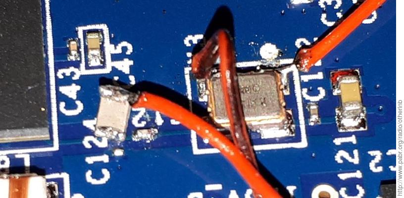
25 MHz output connected to 30 dB amplifier and injected into XTALN of AD9363 via 470 pF decoupling cap
PlutoSDR firmware configured to expect a 25 MHz clock (see [MADEL20190105])
PlutoSDR tuned to 739.675 MHz, sampling at 300 kHz
CW beacon tracked by GNU Radio "PLL Freq Det" block
BPSK beacon coarsely derotated by CW beacon tracker, then demodulated by GNU Radio "Clock Recovery MM" and "Costas Loop" blocks.


[LNBLINEUP] Comparaison de têtes de réception satellite . http://www.pabr.org/radio/lnblineup/lnblineup.fr.html .
[ESTEVEZ20190323] Measuring QO-100 beacons frequency . 2019. https://destevez.net/2019/03/measuring-qo-100-beacons-frequency/.
[AT20190406] A Measurement of Frequency Accuracy and Doppler of the QO-100 Satellite Transponder Beacon . 2019. https://g4jnt.com/QO100_Stab.pdf.
[MADEL20190105] PlutoSDR clock input . 2019. https://tbspace.de/plutosdrclockinput.html.