Othernet (formerly known as Outernet) broadcasts free digital content from the Web over Ku-band geostationary transponders. Their distinguishing feature is that signals can be received with a low-cost demodulator and a bare LNB pointed toward the general direction of the satellites. In February 2020 they announced the Bullseye BE01, a custom LNB with improved frequency stability. It is unclear how this fits in their datacasting strategy. The LoRa modulation should already offer some immunity against frequency errors, but maybe a more accurate LNB will reduce acquisition time. Maybe the improved stability will allow higher data rates or more efficient modulations. Regardless, according to specifications, this LNB should be perfect for amateur radio on QO-100.
Othernet kindly sent me two units, presumably so that I could add the BE01 to my catalogue of satellite LNBs (see [LNBLINEUP]). Obviously the claimed performance and functionality deserve a more in-depth review, hence this article.
According to the product webpage and packaging, the specifications are as follows:
PLL with 2 ppm TCXO . TCXO means Temperature-Compensated Crystal Oscillator. This is a major improvement over the plain crystal oscillator found in contemporary consumer-grade LNBs. All crystal oscillators are affected by temperature; a TCXO measures temperature in order to counteract its effect on the resonant frequency. 2 ppm should guarantees 20 kHz accuracy (or is that only short-term stability ?) at 9750 MHz.
Calibrated to 1 kHz . This means that the absolute frequency error is less than 1 kHz (100 ppb) when the device leaves the factory. But it may drift afterward (see below).
Digitally controlled carrier offset with optional programmer . All crystal-based oscillators drift slowly with age, even TCXOs and OCXOs. The ability to recalibrate means that the LNB can hopefully be kept accurate to a few kHz for weeks at a time. Othernet clarified that the frequency can be adjusted by about ±8 ppm with 200 Hz resolution.
25 MHz output reference . Officially this is intended for monitoring the TCXO, but the wording suggests that the LNB could serve as a frequency reference for other devices. For example, a transceiver with its own 2 ppm oscillator could be off by 1480 Hz at 740 MHz and 4800 Hz at 2400 MHz (typical values for QO-100 downlink IF and uplink, respectively). If the LNB can be calibrated to much better than 2 ppm, it makes sense to synchronize the transceiver to it.
Input frequency 10489 - 12750 MHz, LO frequency 9750 / 10600 MHz, output frequency 739 - 1950 MHz / 1100 - 2150 MHz . This is compatible with European "Universal" LNBs. Note that frequency coverage is usually 10700 - 12750 MHz. The extension to 10489 MHz clearly indicates that the designers had QO-100 in mind.
Frequency stability ±10 kHz at 23°C, ±30 kHz over -20 - +60°C . If I read this correctly, temperature fluctuations can shift the frequency by ±30 kHz and all other effects can add ±10 kHz (but over what time scale ?), therefore worst-case is ±40 kHz (4 ppm). Unfortunately, it is hard to specify the performance of an oscillator succinctly. For example, according to datasheets, an expensive OCXO marketed as "10 ppb" can have an initial error as high as 500 ppb and a guaranteed lifetime accuracy no better than 4.6 ppm (this value comes from NTP stratum 3 requirements). Single-valued stability ratings usually refer either to drift over 24 h in a lab environment, or to temperature sensitivity over the rated range. Detailed specifications will itemize the effect of temperature, initial crystal aging, long-term aging, rapid temperature changes, supply voltage fluctuations, output load variations, static acceleration, vibration, shock, reflow cycles, etc.
Proprietary frequency control system . This explains how the device can claim better stability than a 2 ppm TCXO alone (10 kHz vs 20 kHz). Discussions with Othernet suggest that their TCXOs are actually better than 2 ppm as delivered; presumably the supplier adds a safety margin to account for thermal and mechanical stress during SMT processing, output loading, etc. By merely recalibrating the TCXO after is has been assembled into the LNB, Othernet can certainly cancel some of these effects. Maybe they also implement other tricks such as more sophisticated temperature compensation or even aging compensation.
Gain 50 - 66 dB . This looks bad, but Othernet clarified that this covers variability between individual units and across the whole temperature range. Gain flatness should be 0.25 dB over a typical 30 MHz channel (this is what matters for DVB demodulation) and 5 dB over the full IF bandwidth.
Return loss 8 dB at 739 - 1950 MHz, 10 dB 1100 - 2150 MHz . I am not sure whether this refers to the impedance of the output driver or to the maximum VSWR that it can tolerate from a mismatched load. Anyway these values are on par with other LNBs.
Noise figure 0.5 dB . Most LNB manufacturers claim 0.1 dB but this is commonly regarded as unrealistic. Reputable manufacturers claim 0.3 - 0.7 dB, therefore 0.5 dB sounds reasonable. Othernet confirmed that they don't make random claims here.
Externally the Bullseye BE01 looks like a plain compact PLL LNB. It has a plastic enclosure with a 60 mm horn cap and a 40 mm neck. There are two F-type coaxial connectors. The green connector receives DC power and outputs the IF signal. The red connector outputs the 25 MHz reference.
Inside, a cast-metal body defines the horn, the waveguide and a shielded cavity for the circuit board. Most LNBs are constructed that way. There is a small sealed hole near the cap which is probably involved in weatherproofing at manufacturing time.
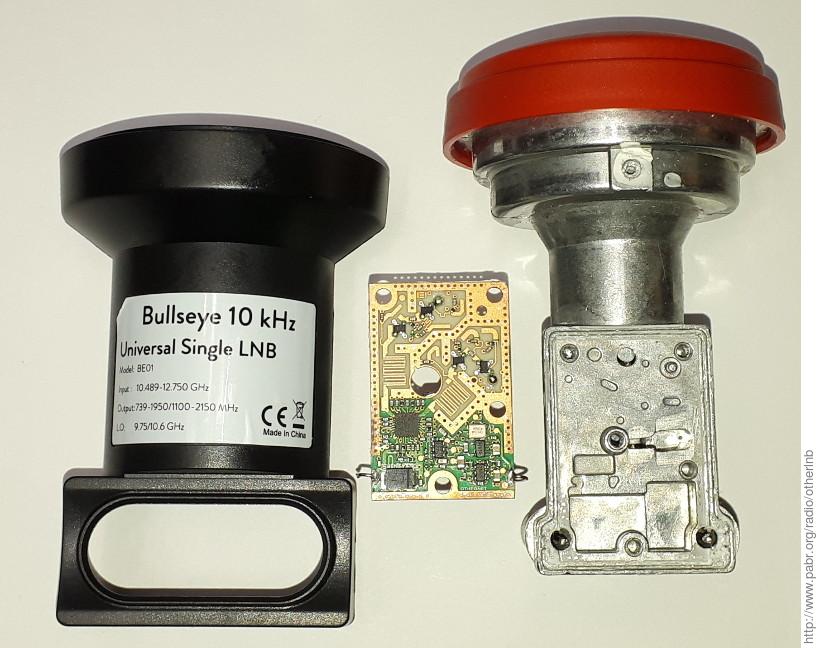
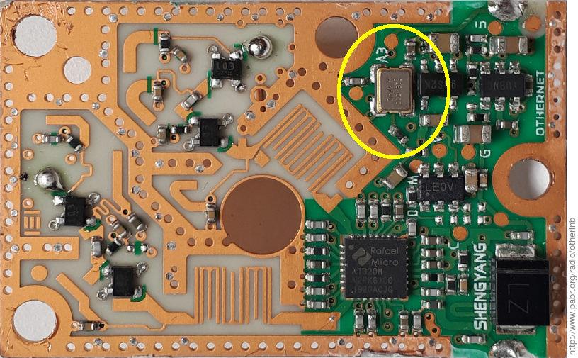
The PCB is only 24x38 mm. The microwave section is based on the Rafael Micro RT320M, also found in the well-known Octagon OTLSO (version 1609). There is no publicly-available datasheet for the RT320M, but Chinese patent CN206712931U reveals the pin configuration. The signal paths are easy to follow; only the biasing voltages for the transistors are routed on internal layers.
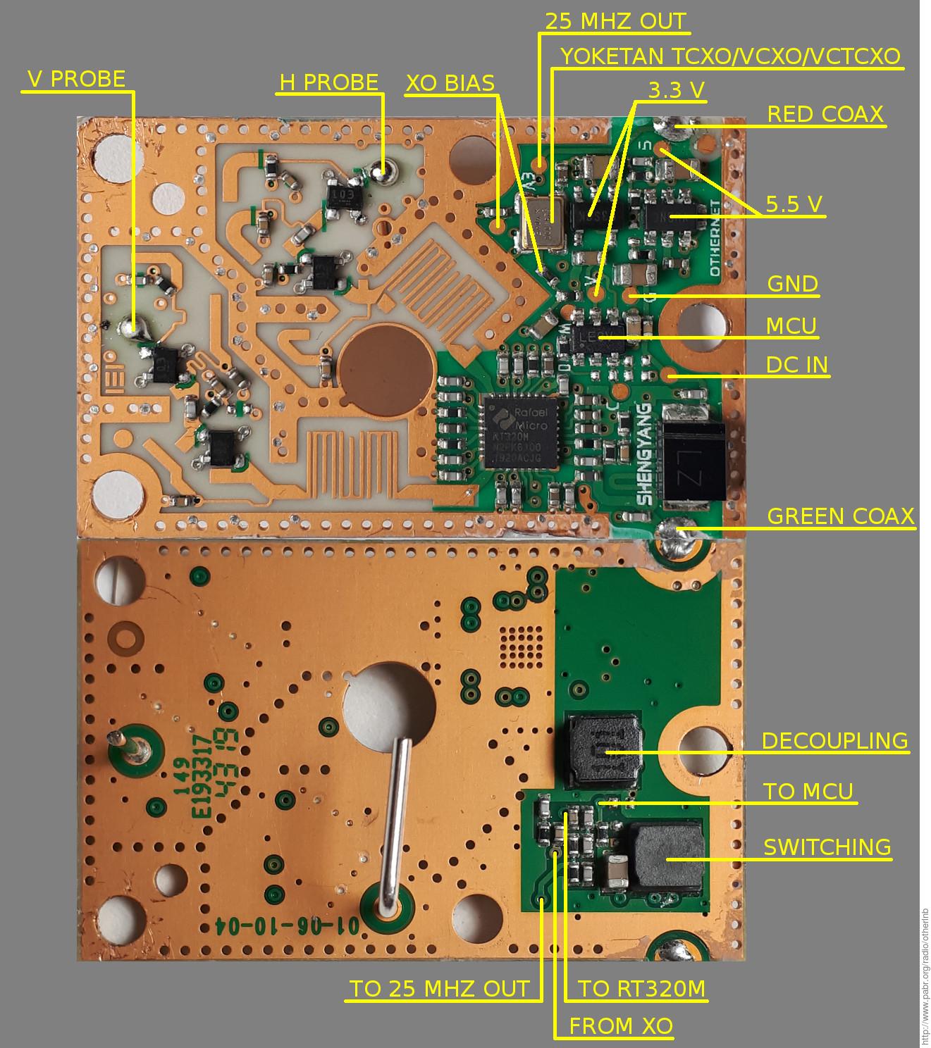
The design departs radically from the mainstream in all other aspects:
The RT320M is powered by a 5.5 V switched-mode voltage regulator, whereas most LNBs use linear regulators. A SMPS produces less waste heat; maybe this helps keep temperature within reasonable limits. Power consumption is the same as a typical LNB, about 1 W, despite the additional functionality.
DC power is tapped from the green coaxial connector via a real SMD inductor. Most LNBs get away with only a wiggly PCB trace; the BE01 has one under the large diode, but presumably this was not enough to protect the IF output from switching noise.
Unlike a standard Twin LNB, the BE01 can only draw power from one port (the green connector with IF output). Othernet hinted that the red connector could tolerate 13/18 VDC if it were connected to a set-top-box by mistake.
The oscillator section is powered by a dedicated 3.3 V linear regulator.
There is a microcontroller which apparently controls the frequency of the oscillator via 15 kHz PWM on pin 1.
Pin 4 of the microcontroller is DC-coupled to the red coaxial connector. Presumably this is how it communicates with the calibration device.
The oscillator appears to be made by YOKETAN. It could be a SV3225A (VCXO) or a customized SO3225T (TCXO).
The accuracy and stability of the BE01 could be evaluated simply by probing its 25 MHz output with a frequency counter. An error of 1 Hz at 25 MHz translates to 390 Hz at 9750 MHz. For meaningful results, the accuracy of the frequency counter should be one order of magnitude better than the quantity being measured. Here, this means about 10 ppb. None of my lab instruments was suitable for this task, so instead I used the QO-100 beacons as a reference and I measured their apparent frequency after downconversion by the BE01.
The stability and exact frequency of QO-100 beacons was a hot topic in early 2019. See [ESTEVEZ20190323] and [AT20190406] for a discussion of NCO artefacts, Doppler shift in geostationary Earth orbit, and possible upconversion offsets in the transponder. In summary, the beacons should be accurate to about 150 Hz (15 ppb), which is good enough for this experiment.
The test setup is as follows:
BE01 mounted on 120 cm dish, powered by bias tee
IF output connected to a PlutoSDR via low-pass filter and attenuator
PlutoSDR TCXO disabled by grounding pin 1
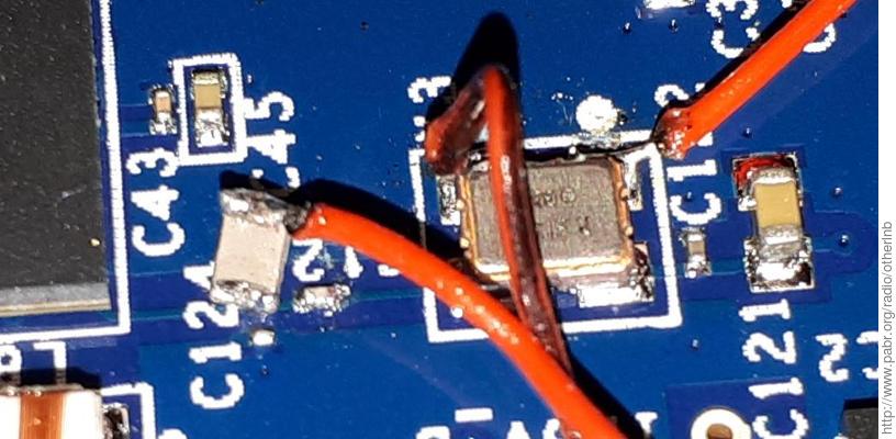
25 MHz output connected to 30 dB amplifier and injected into XTALN of AD9363 via 470 pF decoupling cap
PlutoSDR firmware configured to expect a 25 MHz clock (see [MADEL20190105])
PlutoSDR tuned to 739.675 MHz, sampling at 300 kHz
CW beacon tracked by GNU Radio "PLL Freq Det" block
BPSK beacon coarsely derotated by CW beacon tracker, then demodulated by GNU Radio "Clock Recovery MM" and "Costas Loop" blocks.


The on-board TCXO of the PlutoSDR is rated 25 ppm. Mine is usually off by no more than 4 ppm, i.e. 3 kHz at 740 MHz. This is good enough to enjoy the benefits of the TCXO LNB, but not sufficient to measure its performance. This is why I decided to synchronize the PlutoSDR with the 25 MHz reference. Alternatively, I could have upgraded the PlutoSDR with a better TCXO or an OCXO or a GPSDO.
Note that the 25 MHz output of the BE01 is unbuffered (presumably to allow faithful measurements of TCXO performance) and also heavily attenuated (presumably to prevent load fluctuations from detuning the TCXO). I used a generic wideband LNA to carry the 25 MHz reference to the PlutoSDR over a few meters of coax cable. Gain must be adjusted carefully in order to drive the AD9363 clock input with optimal level.
Frequency offsets were logged for 24 hours in mild winter weather. An outdoor temperature sensor registered between 8°C and 16°C. Stability over that period was ±600 Hz (±60 ppb). Maximum error was 6.8 kHz (700 ppb).
The purpose of the BPSK demodulator was only to confirm that the PLL block remains locked. In theory it could also be used to estimate short-term frequency fluctuations, phase noise, and fading.
The BE01 is supposed to be factory-calibrated to 1 kHz, so the 6.8 kHz offset was surprising, but still within the advertized 10 kHz. Maybe 700 ppb is normal aging for a brand new crystal. Even OCXO manufacturers typically don't specify aging rates for the first 30 days of operation. Presumably crystals take that long to stabilize after reflow soldering.
Simultaneously, I tested a mainstream PLL LNB in the same conditions, except that the attached PlutoSDR was clocked by its on-board TCXO. For reasons already mentioned, this is not optimal, but the error from this TCXO should be ±18.5 kHz worst-case and probably ±3 kHz in practice. The observed frequency errors are much larger than that, so they must come from the LNB.
Note: "PLL LNB" is the historical name for "anything better than DRO", i.e. it refers to the first designs which replaced dielectric resonators with PLL oscillators referenced to plain crystals. Strictly speaking, the BE01 is also a PLL-based LNB, and its TCXO contains a plain crystal; it is the temperature compensation that makes it stand apart.
As usual with PLL LNBs, I had to tune the SDR manually in order to bring the 250 kHz QO-100 band into the 300 kHz digital baseband. With the BE01, the absolute error was well within the ±25 kHz margin, so I did not have to worry about that.
Results suggest that the BE01 was about 30x more accurate and 30x more stable than the PLL LNB during this experiment.
Interestingly, frequency offsets from both LNBs are correlated with ambient temperature, but they move in opposite directions. Maybe temperature affects them in different ways, or maybe the BE01 TCXO overcompensates a little.
The correlation also suggests that temperature is the primary cause of frequency fluctuations. The oscillators don't just drift randomly when temperature is stable.
As far as I know the BE01 is the first affordable mass-produced Ku-band TCXO LNB. These early tests suggest that it can be a game changer for amateur radio and other narrowband applications in the 10 GHz band. The stability and ability to recalibrate should allow even unsophisticated analog stations to tune to a 5 kHz channel and remain there for hours at a time. For SDR stations with beacon-based frequency correction, the absolute accuracy removes the need to oversample by several hundred kHz or to scan for the initial frequency offset.
What remains to be seen is:
How the BE01 compares with TCXO mods already developed by the amateur community for low-cost LNBs; some are available commercially, but presumably only in small quantities due to the manual labor involved. There have been reports of poor phase noise in externally-clocked LNBs, even with expensive oscillators; a LNB with on-board TCXO should not have that problem.
How well the absolute accuracy holds over time, especially during the first few weeks of operation when crystals are known to drift a lot.
Whether the additional complexity affects MTBF in all-weather conditions.
Incidentally, running these experiments helped me realize that the most cost-effective way to improve frequency stability is probably to shield LNBs from rain, wind, direct sunlight and cloudless night skies.
[LNBLINEUP] Ku-band LNB line-up . http://www.pabr.org/radio/lnblineup/lnblineup.en.html .
[ESTEVEZ20190323] Measuring QO-100 beacons frequency . 2019. https://destevez.net/2019/03/measuring-qo-100-beacons-frequency/.
[AT20190406] A Measurement of Frequency Accuracy and Doppler of the QO-100 Satellite Transponder Beacon . 2019. https://g4jnt.com/QO100_Stab.pdf.
[MADEL20190105] PlutoSDR clock input . 2019. https://tbspace.de/plutosdrclockinput.html.