At the time of writing QO-100 is a hot topic in the amateur radio community. Introductory articles should be available shortly from numerous journals and web sites. In summary, QO-100 provides a 8 MHz wide amateur transponder in geostationary orbit, with coverage from Brazil to Thailand. This allows Digital Amateur TV (DATV) activities to expand from line-of-sight paths and local repeaters to a global scale.
This article is intended for readers who would like to get a glimpse of this branch of amateur radio but have no prior experience with DATV and no equipment for space communications. Essentially, the goal is to receive and decode digital video signals which are similar to mainstream satellite TV broadcasts, except that they are produced by amateurs with satellite uplink stations in their backyard. This is somewhat related to Digital Satellite News Gathering (DSNG) where TV reporters provide live coverage and conduct on-site interviews via truck-mounted satellite links.
Ideally reception would be performed with off-the-shelf satellite TV kits (dish, LNB, set-top-box). Unfortunately the frequency bands and data rates are not fully compatible. The amateur radio community has successfully developed several solutions based on modified or dedicated hardware. In this project I explore a different approach in the spirit of software-defined radio (SDR).
For further background information, see:
| Es'Hail-2 (P4-A) project (AMSAT-DL) |
| Receiving guide (BATC) |
| Viva DATV - Home of popular DATV hardware and software |
| Operating guidelines and bandplan (BATC) |
| Band monitor (BATC) |
| DVB-S2 |
Common sense, amateur radio regulations and band policies imply that operators will always use the most efficient combination of power, bandwidth and modulation required to establish communications between two stations. This is easily done with DVB-S2, as this standard allows fine-grained adjustment of modulation and coding parameters. Unfortunately, unless you are in touch with one of the few stations with transmit capabilities, you have no control over these parameters. There are occasional transmissions with power spectral density above the recommended limit, or with unnecessarily slow code rates, but in general, you should assume that signals will always be "barely decodable" by design. So, if you want to listen in on test transmissions, your equipment must be as good as that of the experts. There are only two easy ways around this rule:
Get closer to the peak of coverage of the satellite, which is in the middle of Africa. But this will only give you a couple more dBs of signal-to-noise ratio (SNR); by contrast, in terrestrial communications, you can get a 6 dB advantage by merely sitting halfway between two stations.
Use a bigger antenna. While there is no theoretical limit to how wide you can make a parabolic reflector, amateurs already use the largest TV dishes available at reasonable cost, and oversized models intended for niche applications are expensive and cumbersome to install.
In view of the above, for technically-minded hobbyists, QO-100 DATV reception is a highly challenging and rewarding activity.


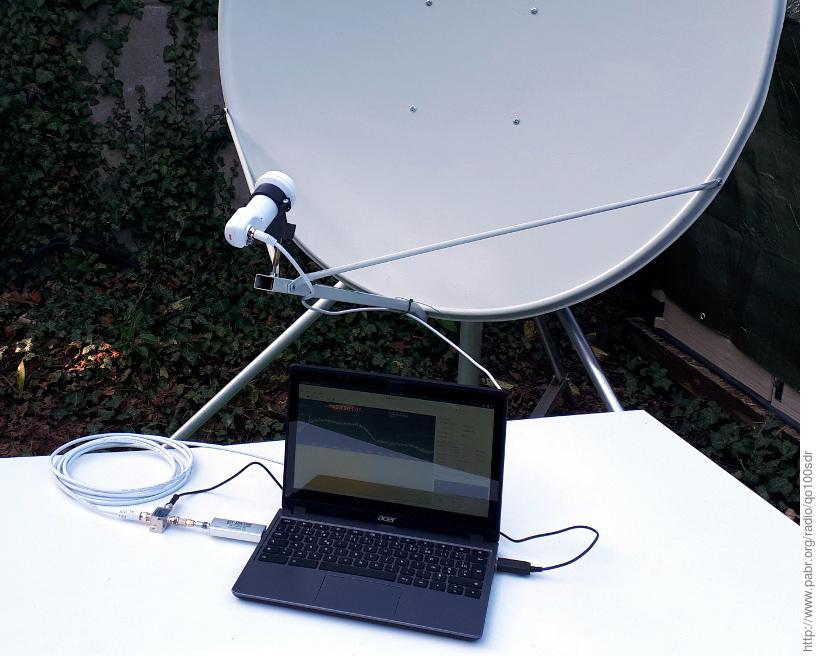
The procedure described in this article was tested in western Europe with a low-cost 120x110 cm offset satellite TV dish antenna. A slightly smaller antenna might work now, but it should be noted that as QO-100 attracts more simultaneous users, the power budget of the transponder may be spread across two to three times as much bandwidth. This would reduce signal strength by 3 to 5 dB. Therefore, it is a good idea to choose the largest dish you can get.
Strictly speaking, it is useless to enlarge the dish beyond the point where noise from the transponder exceeds noise from your LNB. A good 120 cm dish can see the noise floor of the transponder when only the 2 Mbaud beacon is active. I estimate that a 180 cm dish will be enough to see the noise floor when the band is fully occupied.
Satellite dishes vary not only in size, but also in build quality. As a rule of thumb, for optimal gain, a Ku-band dish must have an absolute geometrical accuracy of 3 mm. It is easy to see that a large pressed-metal reflector cannot keep an exact shape. Fiberglass-backed dishes are more rigid, but heavier and more expensive.
Many stations have carefully-optimized 2 m dishes that they also use for transmitting; this sets a baseline for the most extreme signals that will be seen on this band. These signals will not look stronger or weaker than the others; indeed, by policy, transmitters should not exceed the power spectral density (PSD) of the beacon, and power-limited transmitters are encouraged to reduce their symbol rate until they match the maximum PSD in order to avoid wasting valuable spectrum. Rather, these signals will use more aggressive modulation and coding schemes which yield higher data throughput but require up to 16 dB of SNR.
Note that if your dish turns out to be too small or too lossy for this project, you can always fall back to experimenting with the QO-100 narrowband downlink which is stronger and carries CW, voice and low-bandwidth digital transmissions. Also, a poor Ku-band reflector can be good enough for S-band, thanks to the weaker requirements on geometrical accuracy.


The LNB at the focal point of the reflector receives and amplifies the Ku-band (> 10 GHz) signals. It also shifts them to a more manageable intermediate frequency range (IF, 950 - 2150 MHz). See [LNBLINEUP] for background information on LNBs.
Any modern "universal" LNB is worth testing for this project, provided that it is a "PLL" model and not an older "DRO" design. The Octagon OTLSO is popular in the amateur radio community.
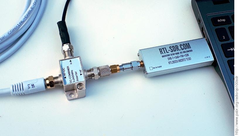
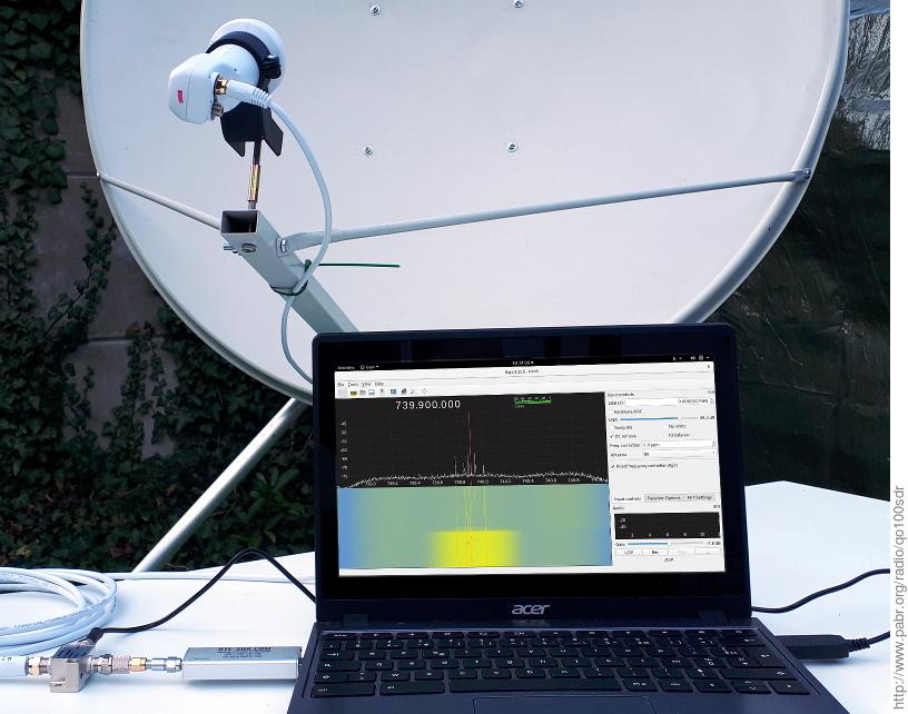
Mass-market LNBs must be powered through the port that carries the IF output. This is usually done by inserting a small device called a bias tee between the LNB and the receiver.
"Quattro" LNBs can be powered through a dedicated port, without a bias tee. This approach has not been validated yet.
The nominal voltage for European "universal" LNBs is 13/18 V, but 12 V is fine and most models will work down to 9 V. Current consumption is typically 100 - 200 mA. I use a USB-powered DC-DC converter for convenience, but any regulated power supply with suitable characteristics should do.


Satellite LNBs are designed to push 1 GHz worth of HDTV signals through dozens of meters of mass-market coaxial cable. They typically output about 1 mW - possibly more in unusual circumstances. By contrast, most SDR receivers are sensitive enough to pick radio signals from a simple wire antenna. Hence, it is a good idea to insert an attenuator. This will prevent saturation and reduce the risk of damage to the SDR device. A 30 dB model works for me.
Attenuators can be cascaded. They are available with F-type connectors from satellite TV suppliers, and with SMA connectors for professional applications.
It is also a good idea to insert a low-pass filter with a cut-off frequency between 800 MHz and 2000 MHz, between the bias tee and the SDR. Otherwise, with some wideband SDR receivers, the third harmonic of the L.O. can downconvert signals from 2220 MHz IF (11970 MHz RF) into the baseband.


Any SDR receiver capable of tuning to 700 - 800 MHz and capturing 2.4 million samples per second should work. Devices that can capture more than 4 million samples per second (or twice the symbol rate of the signal of interest) yield more robust results.
This article focuses on rtl-sdr dongles because they are inexpensive. A well-shielded variant with a TCXO and SMA connector is worth the extra $15 over a basic model.
The crucial component for this project is leandvb. I wrote the initial version in early 2016 to receive DVB-S transmissions from the International Space Station ([SOFTDATV]) and I added DVB-S2 support in 2018 in anticipation of Es'Hail 2 / QO-100. You will need to compile leandvb and a third-party LDPC decoder, ldpc_tool. See [LEANDVB] for installation instructions, documentation, and full credits.
You will also need software to control your SDR device. The only requirement is that it must be able to save I/Q samples in uint8, int16 or float32 format. Instructions below refer to the rtl_sdr command-line utility and to the gqrx graphical application.
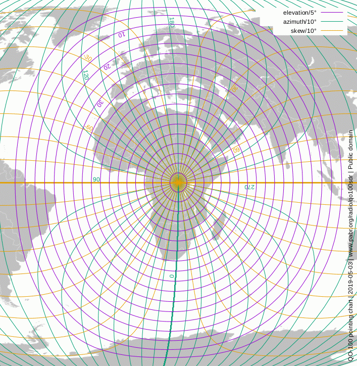
Assemble the dish and point it toward QO-100 at 26°E. There are plenty of tutorials on how to point satellite TV antennas. The main difficulty is that manufacturers rarely specify offset angles, and swivel mounts are not labeled accurately. So, the best approach is to pan the dish toward the proper azimuth, but not worry too much about elevation yet.
Warning . When using a bias tee, the powered side (usually labelled "ANT" or "HF+DC") goes toward the LNB. Do not ever connect it to a SDR receiver; this could destroy the analog front-end and possibly damage the host computer as well.
Figure 2. SDR setup
| LNB cable, bias tee, 30 dB attenuator, rtl-sdr receiver, Linux laptop. |
| USB DC-DC converter not shown. |
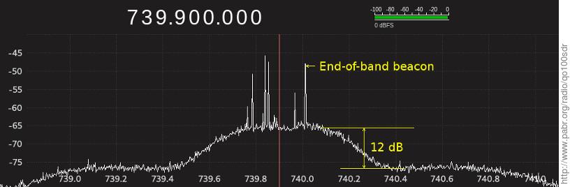
To align the dish, we will detect the narrowband transponder, which happens to be very strong and to fit within the bandwidth of a rtl-sdr dongle. Install the LNB for vertical polarization: point the cable down, then apply the skew angle. A skew value of -20° is illustrated in the picture below. Tune the SDR receiver to 739.675 MHz; this is the center of the narrowband downlink in the IF. Now tilt and wiggle the dish until you see a signal. Since there are currently no other geostationary transmitters at that frequency, this is actually easier than pointing a TV antenna toward the right satellite. You may want to move the LNB around its designated position, in case the geometry of your dish is inaccurate. Eventually you should see this:
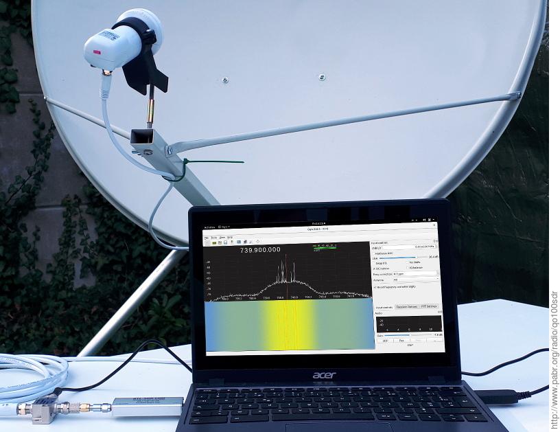
In this spectrum plot we note that:
The noise floor of the transponder is 12 dB above the noise floor of the receiver. This is excellent, but not surprising considering that this dish is oversized for receiving the QO-100 narrowband downlink.
The signal is about 225 kHz higher than it should be. This results from the combined inaccuracies of local oscillators in the LNB and in the SDR device. An exact value can be determined by looking at the end-of-band beacon which is always on and has a nominal frequency near 739.7975 MHz. The same frequency correction should be applied for all further tuning operations.
Now switch the LNB to horizontal polarization, i.e. turn it 90° either way. Adjust the angle until the signal is as weak as possible in the spectrum display. This will yield optimal isolation between the two polarizations.
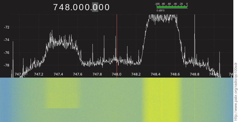
Next we will look at the video beacon of the wideband downlink, which is centered at 742.5 MHz in the IF. Since the beacon is more than 2 MHz wide, we can't really recognize its shape with a rtl-sdr dongle. So, instead, we tune to its upper edge at 743.5 MHz (plus or minus the correction determined earlier).
In this spectrum plot we can measure the gap between the beacon and the noise floor. This is the (C+N)/N (carrier-plus-noise to noise) ratio. If you get 7 dB or more, there is hope of demodulating the signal,
Table 1. (C+N)/N to C/N conversion table
| (C+N)/N (dB) | C/N (dB) |
|---|---|
| 1 | -5.87 |
| 2 | -2.33 |
| 3 | -0.02 |
| 4 | 1.80 |
| 5 | 3.35 |
| 6 | 4.74 |
| 7 | 6.03 |
| 8 | 7.25 |
| 9 | 8.42 |
| 10 | 9.54 |
Now, tune to 742.5 MHz (plus or minus correction) and record about 30 s worth of I/Q data at 2.4 Msamples/s. In gqrx this is done with Tools -> I/Q recorder or Ctrl+I. Note that rtl-sdr dongles will silently drop samples if the host computer cannot keep up with the data rate. This will cause demodulation to fail for no apparent reason. Hence, it is recommended to save to a ramdisk (/tmp, /var/tmp or /mnt/tmp depending on OS variants),
to shut down any unnecessary application, and to slow down spectrum waterfall animations while the I/Q capture is in progress.
To demodulate I/Q data recorded by gqrx, adapt the following command:
$ leandvb --f32 -f 2400e3 --sr 2000e3 --sampler rrc --rrc-rej 30 --standard DVB-S2 --ldpc-helper ldpc_tool --modcods 0x0040 --framesizes 0x01 -v -d --gui < /tmp/gqrx_YYYYmmdd_HHMMSS_742ffffff_2400000_fc.raw > /tmp/video.ts
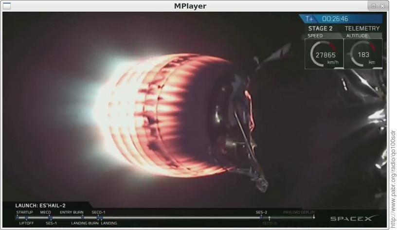
Then, decode the MPEG TS data with a video player. You should see footage of the launch of the satellite and other promotional material.
$ mplayer /tmp/video.ts
$ vlc /tmp/video.ts
To do the same with a rtl-sdr dongle from the command line, adapt these commands:
$ rtl_sdr -f 742.5e6 -s 2400000 /tmp/video.iq
$ leandvb --u8  -f 2400e3  --sr 2000e3  --sampler rrc  --rrc-rej 30  --standard DVB-S2  --ldpc-helper ldpc_tool  --modcods 0x0040  --framesizes 0x01  -v  -d  --gui  < /tmp/video.iq  > /tmp/video.ts
$ mplayer /tmp/video.ts
$ vlc /tmp/video.ts
Next you can try live demodulation. Add --inpipe as shown below to prevent buffers from overflowing. Add --nhelpers to run several LDPC decoders in parallel; use 6 decoders if your CPU has 8 cores, or 3 decoders if it has 4 cores.
# echo 32000000  >  /proc/sys/fs/pipe-max-size
$ rtl_sdr  -f 742.5e6  -s 2400000  -  |  leandvb  --inpipe 32000000  --u8  -f 2400e3  --sr 2000e3  --sampler rrc  --rrc-rej 30  --standard DVB-S2  --ldpc-helper ldpc_tool  --nhelpers 6  --modcods 0x0040  --framesizes 0x01  -v -d --gui  |  vlc -
Once you have successfully received the video beacon, you can search for actual DATV signals elsewere in the wideband downlink. Optimal SDR settings for decoding these signals have not been validated yet. Note: Options --modcods 0x0040 --framesizes 0x01 are a workaround for a known bug; omit them when demodulating other streams.
With some UNIX scripting skills and a fast computer, it should be possible to set up leandvb to scan through the QO-100 bandplan and possibly decode multiple video streams simultaneously. This is left as an exercise for the reader. Note that due to how LDPC decoding works, CPU usage increases dramatically as SNR approaches the limit for decodability.
If you follow discussions among QO-100 users, you will notice that their hardware DVB-S2 receivers can demodulate signals at lower SNR than your SDR setup. leandvb currently needs a few dBs of margin. This is a trade-off between sophistication and realtime throughput in the signal processing and error decoding algorithms. Hopefully the gap will shrink over the next few months.
[LEANDVB] leandvb: A lightweight software DVB-S demodulator . http://www.pabr.org/radio/leandvb/leandvb.en.html .
[SOFTDATV] SDR reception of Digital Amateur TV from the ISS . http://www.pabr.org/radio/softdatv/softdatv.en.html .
[LNBLINEUP] Ku-band LNB line-up . http://www.pabr.org/radio/lnblineup/lnblineup.en.html .