


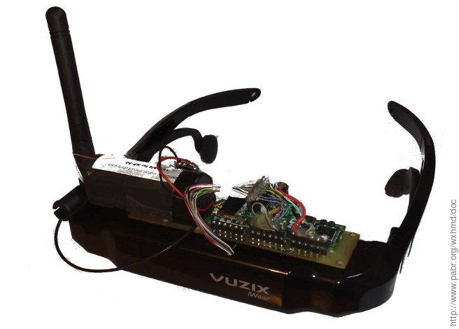


The Vuzix VR920 is a rather high-end HMD (400 EUR) intended for desktop 3D applications:
Two 640x480 Kopin display modules
DB15 VGA analog video input
USB powered (500 mA @ 5 V nominal, works down to 3.7 V)
Built-in stereo audio headphones and mono microphone (USB audio profile)
3-axis accelerometer and 3-axis magnetometer (USB HID profile)
Full specifications: http://www.vuzix.com/iwear/products_vr920.html
TI OMAP3530, max 600 MHz (runs at 500 MHz by default)
256 MB RAM, microSD flash
WiFi, Bluetooth
USB OTG (supplies 100 mA max)
LCD digital video output signals @ 1.8 V
Must be interfaced via two 70-pin 0.4 mm-pitch SMD connectors.
Full specifications: http://www.gumstix.com/store/catalog/product_info.php?products_id=227
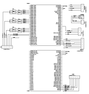
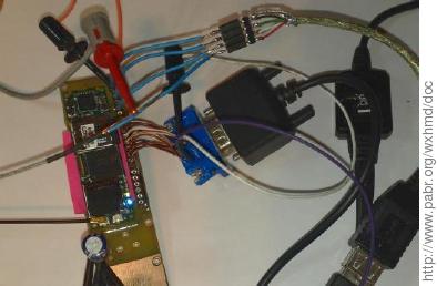
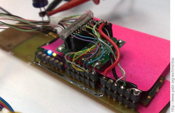
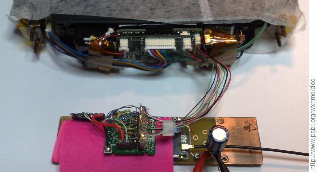
To bridge the electrical and mechanical gap between the Overo and the VR920, I had to design and build a small breakout board with decently sized connectors for power and USB, and simple resistor-based digital-to-analog converters (DACs) for analog video output. The DACs are connected to the digital LCD output of the OMAP and produce 12 bpp signals (4 bits per component). LCD sync signals from the OMAP are routed directly to their matching VGA pins (the VR920 happens to accept 1.8 V signals instead of 5 V signals). Software on the OMAP does the rest. Actually, the OMAP cannot generate fully VGA-compliant sync signals (I suspect HSYNC pulses are a bit too short), but the VR920 is quite tolerant there as well.
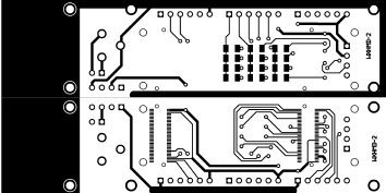
The double-sided PCB was designed with gEDA gschem, laid out with gEDA PCB, and etched by Direct Inkjet Resist Printing (see [PCBPRT]).
I had to convert the Overo pinout and footprint to gEDA format: OVERO.sym, OVERO.fp. These files are derived from specifications published by Gumstix under a Creative Commons Attribution-ShareAlike2.5 license. Some of the work was done manually, so there may be errors.
Since the USB OTG port of the Overo can supply only 100 mA,
the HMD is powered by VSYSTEM instead of USBOTG_VBUS.
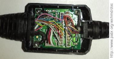
I assumed very early in the project that the 13-pin connector inside the VR920 would receive raw VGA and USB signals. But it turned out that the cable, which splits into a VGA branch and a USB branch, contains a small circuit board which pre-processes VGA sync signals.
I did not bother trying to figure out whether the OMAP could generate a suitable composite sync signal (apparently non-standard). I simply merged this board into the design. Besides, I could not find a source for the 13-pin, 1.0 mm-pitch board-to-wire connector in the VR920. Sacrificing the cable helped solve that problem too.
USB . The USB stack of the VR920 tells the host that it needs 500 mA, and therefore Linux will disconnect it immediately. The usual workaround consists in inserting a powered USB hub. Instead, since we are powering the VR920 directly from VSYSTEM, we can safely force Linux to ignore USB power checks with usb_ignore_power.patch.
Frame-buffer . The Linux frame-buffer resolution should be set to 640x480 in the u-boot environment.
OMAP LCD configuration . These commands configure the OMAP LCD subsystem so that it generates VGA-like signals:
DISPLAY=:0.0 xset -dpms         # Prevent the LCD silicon from powering down; otherwise we cannot access its registers.
devmem2 0x480504fc w 0x00003000 # Polarities
devmem2 0x48050464 w 0x02f00f3f # HSYNC
devmem2 0x48050468 w 0x02000901 # VSYNC
devmem2 0x4805047c w 0x01df027f # Size
killall Xorg                    # Force changes to take effect.
HID
. The proper way to access the tilt sensors is through /dev/hidraw,
which requires recompiling the Gumstix Linux kernel with CONFIG_HIDRAW=y. Then, measurements are read in chunks of 17 bytes containing six 16-bit little-endian values:
root@overo:~# hexdump -e '4/1 "%02x " 6/2 " %4d " 1/1 " %02x" "\n"' < /dev/hidraw0
00 02 02 00   -1   403   -60    82   421   189 ab
00 02 02 00   -9   374   -68    65   400   175 ab
00 02 02 00   -8   394   -65    62   396   174 ab
00 02 02 00  -19   378   -78    35   364   158 ab
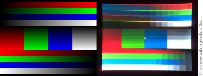
The ramps are almost monotonic, even with resistors from the E12 series (10 % matching accuracy). Maybe it would have been worth using 5 bits or more per component after all.
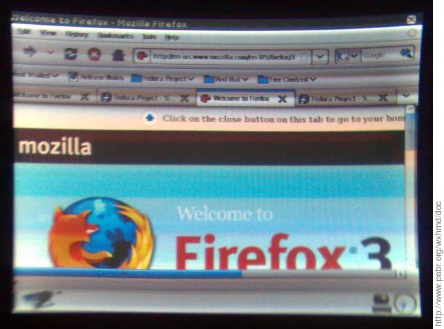
The poor display quality in these photos stems largely from signal bleeding caused by the low-tech DACs, but also from the difficulty of positioning the camera exactly at the focus of the HMD optical assembly.
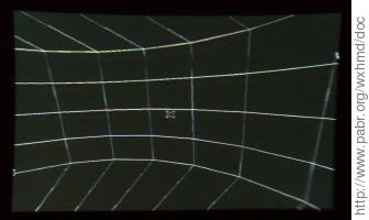
vroom920.c demonstrates stereoscopic mode and head tracking. It displays a wire-frame cylindrical room around the user.
Disclaimer . This prototype probably violates most applicable technical interoperability standards and regulations regarding user safety and electromagnetic interference.
DACs . In hindsight, I could have used real high-speed video DACs. But since this was my first SMD hardware project with an inkjet-printed PCB, I chose to avoid complications; resistors are easier to source and to troubleshoot.
GPIO . Resistor-based DACs on GPIO outputs probably stretch the electrical ratings of the OMAP a little, but this does not make much difference since it was already running quite hot. If this fries my Overo module eventually, I will report it here.
Battery life . The systems draws 1 A with no power optimizations. This is acceptable since nobody would want to spend more than a few minutes with two pulsed microwave RF transmitters, an overheating lithium battery and eye-straining optics strapped to their forehead anyway.
Improve integration . The VR920 circuit board has many sophisticated features that we do not really need for this project, such as sampling and rescaling of various VGA variants and resolutions, and even on-screen overlay menus. It is certainly possible to discard it and drive the Kopin display modules directly. [VOGL2008] does it with the 320x240 model, which has a slightly different analog RGB interface. The main difficulties would be working with 9 V signals, implementing the row polarity inversion, and sourcing the ZIF flex connectors.
[PCBPRT] pcbprt - Experiments in inkjet PCB printing . http://www.pabr.org/pcbprt/pcbprt.en.html .
[VOGL2008] Gumstix Video out board :: Kopin K230LV adapter . http://pervasive.researchstudio.at/portal/node/49 .